Summary
The GEOL_ROSEDIAGRAM command in GeoTools enables users to create Rose Diagrams and Stereonets for analyzing dip-strike orientations, making it an essential tool for structural geologists, geotechnical engineers, and GIS professionals in BricsCAD, AutoCAD, ZWCAD and ARES Commander.
GeoTool -> Geological/Mining Tools -> Dimensional Stone -> Draw Rose Diagram/Stereonet
Key Features Include:
- Multiple Rose Diagram Types:
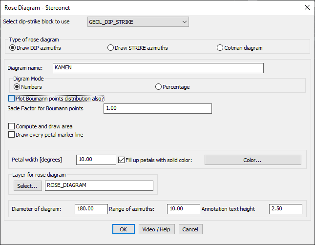
- Draw DIP azimuths – Visualize the dip direction of geological structures.
- Draw STRIKE azimuths – Represent strike orientations of rock formations.
- Cotman diagram – Alternative method for stereonet visualization.
- Customizable Diagram Settings:
- Assign a diagram name for easy reference.
- Choose between Numbers or Percentage for data representation.
- Advanced Geological Data Integration:
- Option to plot Boumann point distribution for statistical analysis.
- Apply a Scale Factor for Boumann points to refine visualization.
- Graphical Enhancements:
- Adjust petal width (in degrees) for detailed representation.
- Enable solid-colored petal fill for clarity and better visualization.
- Compute and draw the total area covered by the rose diagram.
- Option to draw marker lines for each petal for enhanced readability.
- Layer & Display Controls:
- Assign a specific CAD layer for the rose diagram (e.g., “ROSE_DIAGRAM”).
- Define diagram diameter, azimuth range, and annotation text height.
Benefits:
This tool is highly useful for structural geology, fault analysis, and directional data representation, allowing users to visualize geological trends effectively for interpretation and decision-making.