Key updates of GeoTools-CADPower V 19.05 / 19.06 / 19.07
Bengaluru, India
The past couple of weeks has been hectic at the GeoTools-CADPower development camp here.
We are again on a mission to improve the delivery content of our tools and also strengthen the documentation of our products. You will begin to see the results in the next couple of months as a new mission has been put in place to fast-track the tools and their delivery experience.
In this post, I am summarizing some of the key developments in updates V 19.05, 19.06 and 19.07 of GeoTools & CADPower.
CADPower V 19.07 Update:
** Enhanced command: CP_COPYLYR / COPYLYR / COPYTOLAYER: (Menu: CADPower -> Layer -> Copy from one layer to another):
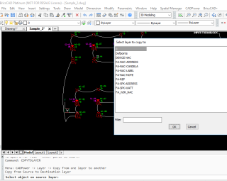
The COPYTOLAYER command, as users expect it to be, now in BricsCAD
In the previous (19.04) update, we announced that the COPYLYR command is now a FREEWARE command.
In this update, we enhanced it further. We have added a new alias called COPYTOLAYER.
Now, CP_COPYLYR, CPOLYLYR and COPYTOLAYER all do exactly the same thing – i.e to enable copying of one layer contents to another.
Additionally, the COPYTOLAYER command now allows the source layer to be specified by picking an object and the target layer can now be selected from a dialog box.
This is in line with the expected behavior as happens in AutoCAD.
** Enhanced command: CP_LYRS2DWG: (CADPower -> Miscellaneous -> Export -> Layers to DWG):
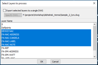
The CP_LYRS2DWG command now is able to export multiple selected layers into one single drawing.
The earlier workflow would only automatically create a single DWG for each layer of the drawing. Both the options are now available.
** Enhanced command: CP_IMPEX : (Menu: CADPower -> Export -> Import/Export points and lines):
A new option has been added in the ‘Import’ section to recognize and process points as geographic coordinates in the (Degree-Minute-Second (DMS) format).
If this option is checked, all incoming coordinate data is checked if it fits the format of DMS and it is accordingly processed into the X or Y coordinate value of the point.
Supported DMS formats are: 12 56 27.3287 (degrees-minutes-seconds) or 12 56.45 (degrees and decimal minutes)
* In the ‘Import’ option, a new format called ‘Other’ has been introduced. This allows a wider range of coordinates and other data combinations in the import file to be supported and processed.
For example, if your X & Y (or E & N) coordinates start only at the 4th column of the file, you can now skip columns while reading using the I (for Ignore) parameter in the ‘Other’ file format.
For example, IIIXYZ or IIIEN can be used to process an input file where the first three columns are ignored and the X & Y coordinates are defined in the 4th and 5th columns.
** Important enhancements to BricsCAD+ menu (for BricsCAD-CADPower users only):
** Context menus: Right-Click action
This is seriously important for first-time BricsCAD users. Two of the most important requests we have seen are ‘Hatch Generate Boundary’ (upon right-click on HATCH entity) and Add Vertex / Convert to Arc / Delete vertex (upon right-click on polyline segment).
Both have been adequately implemented in BricsCAD using CADPower, and it is FREEWARE, available to all, forever.
And lastly, we would like to remind you that this list is just the beginning. If you are missing some of your favorite AutoCAD short-cuts and hacks as a convenient right-click features, let us know and I will try and put them here.
GeoTools V 19.07 Update
** New command added: GT_GEIMPORTPOINT (GeoTools -> Geographic -> GEIMPORTPOINT (Google Earth Point Import)):
The GT_GEIMPORTPOINT command is a tool used to capture the Lat-Long and UTM coordinates of a picked location in Google Earth and create the same in the CAD drawing as a GPS control block. The block name is GT_GPS_POINT and has three attributes:
- UTM_COORDS
- LL_COORDS
- POINT_NUMBER
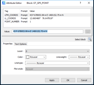
The GPS Point block and its Lat-Long / UTM attributes captured in CAD
This command is somewhat similar to the GT_GEIMPORTIMAGE command. It will take you through a step-by-step assisted procedure that will ask you to setup your Google Earth software correctly at the desired point, once with Lat-Long as the units and again with UTM as the units, and the coordinates of the same point are captured to clipboard and transferred to the CAD.
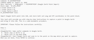
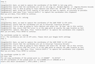

Transcript of actual step-by-step instructions to import a geo-referenced point form Google Earth
A block called GT_GPS_POINT is created in CAD with the above three attributes. Having captured the Lat-Long and UTM coordinates of the same point from Google Earth, this block now serves as a GPS Control point, and can be used for various purposes, including rubber-sheeting of vector data.
** New command added: GT_GERSHEETWITHCTRLPOINTS (Menu: GeoTools -> Geographic -> Rubber Sheeting with Drawing Control Points):
The GT_GERSHEETWITHCTRLPOINTS command complements the GT_GERSHEET command.
This command requires two pre-existing control points in the drawing (defined as block named GT_GPS_POINT) and they are used to rubber-sheet and fit the data from Lat-Long coordinates to UTM or vice-versa.
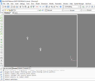
The control points are defined as blocks created using the GT_GEIMPORTPOINT command.
This is an attributed block which has both the geographic and UTM coordinates of the point captured from Google Earth.
** Enhanced command: GT_IMPEX : (Menu: GeoTools -> Export -> Import/Export points and lines)
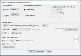
The updated GT_IMPEX / CP_IMPEX main dialog
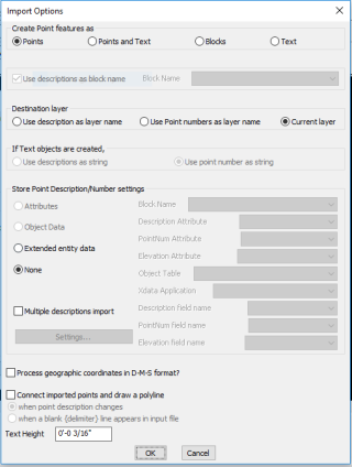
The updated Import Options dialog box
A new option has been added in the ‘Import’ section to recognize and process points as geographic coordinates in the (Degree-Minute-Second (DMS) format).
If this option is checked, all incoming coordinate data is checked if it fits the format of DMS and it is accordingly processed into the X or Y coordinate value of the point.
Supported DMS formats are: 12 56 27.3287 (degrees-minutes-seconds) or 12 56.45 (degrees and minutes)
n the ‘Import’ option, a new format called ‘Other’ has been introduced.
This allows a wider range of coordinates and other data combinations in the import file to be supported and processed. For example, if your X & Y (or E & N) coordinates start only at the 4th column of the file, you can now skip columns while reading using the I (for Ignore) parameter in the ‘Other’ file format.
For example, IIIXYZ or IIIEN can be used to process an input file where the first three columns are ignored and the X & Y coordinates are defined in the 4th and 5th columns.
Want to know more about DesignSense, BricsCAD?
- BricsCAD V18: Trial download
- BricsCAD V18 Shape: Free download
- BricsCAD Communicator V18: Trial download
- CADPower V19 for BricsCAD: EXE (-or-) ZIP (Linux/Mac compatible)
- CADPower V19 for AutoCAD: EXE (-or-) ZIP
- GeoTools V19 for BricsCAD: EXE (-or-) ZIP (Linux/Mac compatible)
- GeoTools V19 for AutoCAD: EXE (-or-) ZIP
Key Contacts: rakesh.rao(at)thedesignsense.com / +91-9243438300 / +91-8073279755
Follow us on Twitter: http://www.twitter.com/rakesh_rao
