Drawing a CAM Profile (Knife Edge Follower Diagram) and Displacement Diagram in AutoCAD-BricsCAD
Bengaluru, India
In Version 20.05 of CADPower, we introduced the function to draw a CAM Profile.
The addition of this feature empowers CADPower with a productivity tool that will make it appealing to the manufacturing industry.
A cam is a rotating or sliding piece in a mechanical linkage used especially in transforming rotary motion into linear motion.[1][2]
It is often a part of a rotating wheel (e.g. an eccentric wheel) or shaft (e.g. a cylinder with an irregular shape) that strikes a lever at one or more points on its circular path.
The CAM Profile tools in CADPower is available under the Draw Tool, Ruke Based and allows the CAM displacement diagram and the CAM Profile (Knife Edge follower diagram) to be drawn in your AutoCAD or BricsCAD platform.

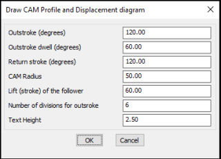
CP_CAM_PROFILE dialog box allows entry of key parameters
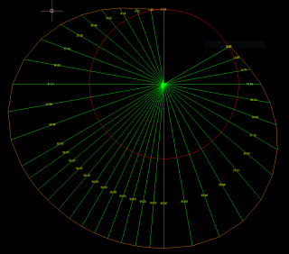
There are two diagrams created – the displacement diagram and the actual CAM profile (knife edge follower diagram).

CAM displacement diagram

The CAM profile (Knife edge follower) diagram
This is the first version of the tool and is a simple implementation.
I request users to try this out and give me your feedback, wishlists and inputs. We would like to improve the command further to do more.
