CADPower V23 as a Space Planning Tool

If you are in the business of placing, sizing and counting rectangular tiles or blocks, this article is for you!
One of the most common requirements of a civil engineer, architect or construction professional is the ability to place tiles (or blocks) within a specified area, optimize it and generate a quantity takeoff summary out of it.
CADPower can handle that requirement very cleverly using the CP_TILEPLACE, CP_SCLEDIT and CP_TILECOUNT commands.
The space planning tools that we are going to discuss in this post relate to tile filling within an area and subsequent export to Excel.
A CAD drawing and Excel are closely connected. They are part of the same design-draw-fabricate-build workflow. 90% of all design data and manufacturing quantities are extracted from the drawing and sent to Excel for downstream processing, ordering, estimation, proposals, manufacturing & fabrication. So, it is only natural that many of CADPower functions export to Excel directly.
CADPower has always had a functioning Bill of Materials / Quantity takeoff tool (CADPower -> BOM/QOQ Tools -> BOM Generator).
This tool creates a CSV file which can be easily exported to Excel.
The CP_TILEPLACE command is closely related can can be used to create scaled blocks which can be used for quantity takeoff computations.
The CP_TILEPLACE command in CADPower
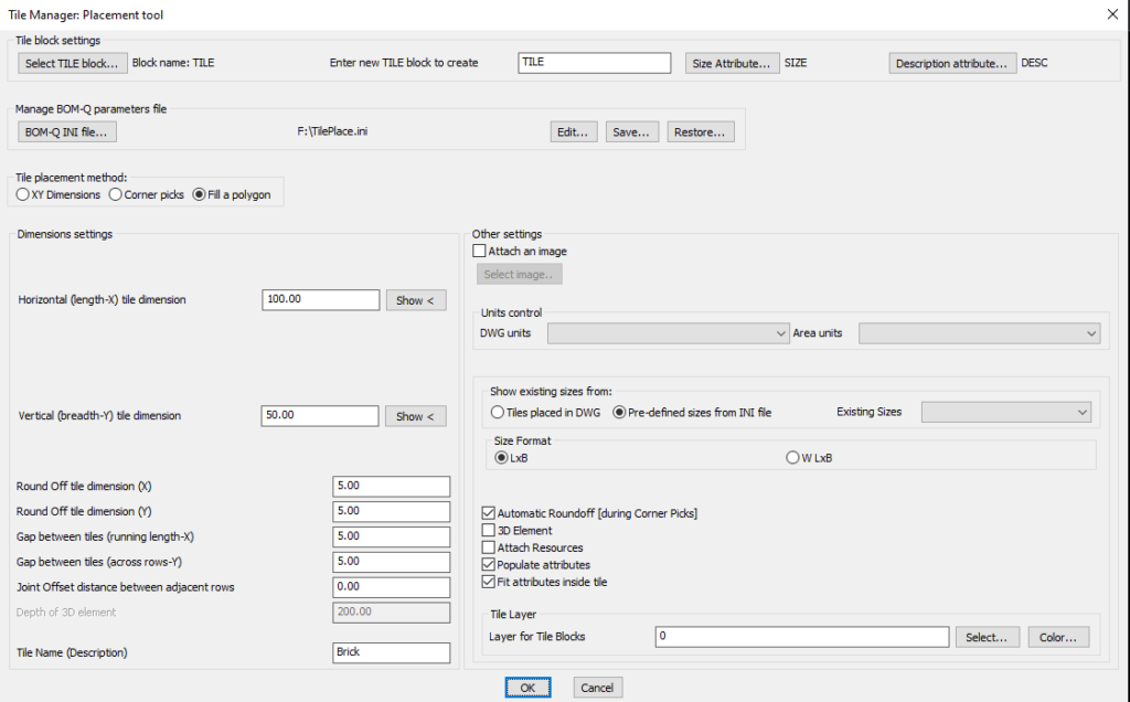
The CP_TILEPLACE command in CADPower is used to place a tile (or block or panel) (a rectangular element) to fill a given closed polygonal area.
The main dialog box can look a bit overwhelming at first but I am here to explain how it works and make it simple for you.
This tool works on a rectangular-shaped block as the main entity defining the tile layout. This block is created at unit scale and placed at different X and Y scales as per the size of the panel. The tile block can be created (new) automatically by entering the name in the space provided in the dialog box above.
Enter new TILE block to createThe tile block is created with two attributes – SIZE and DESC, which store the size value and a user-specified description.
You can also use your own custom-defined block, as long as it is defined in unit scale, and has a geometric shape of a 1×1 square with its insertion point at the lower left corner.
You can define your own attributes for size and description, and specify the same in the dialog box.
The program operating parameters are stored in an INI file, which can be used for retrieval in later sessions on this computer or another.
Tile Placement Method
 - X and Y dimensions
 - Corner picks
 - Fill a polygon
You can place a tile in different ways. The first two options are manual methods, while the third option (most popular) allows you to select a closed polyline and fill it with the specified rectangular tiles.
Before you can start placing the tiles, you need to assign the correct X and Y sizes for your tile, and also the rounding off values and gap distance between tiles. These are specified in the dialog box as ‘Horizontal (length-X)’ and ‘Vertical (breadth-Y)’ dimensions. There is also a ‘Show <‘ button which allows you to specify the dimension by picking two points on the screen.
You can also create a staggered offset between the rows of tiles by specifying the joint offset distance. By default, this value is 0.0 (no offset).
Attach an imageOften, designers want to embed an image (most likely a tile pattern) in each of the tiles. You can achieve this by selecting and adding an image which becomes part of the tile block that is defined.
Show existing sizes from
- Tiles placed in DWG
- Pre-defined sizes from INI file
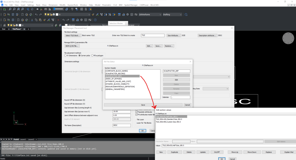
Once you start placing the tiles in your drawing, you will build a collection of different sized tiles. You can display the list of all such inserted tiles from your drawing by clicking on the above option. You can also pre-define the tile sizes that you want to use in your project. This must be done in the INI file (see below), and if you have done so, you can access that list here by clicking on the appropriate option.
In the image below, you can see three sizes defined explicitly in the INI file.
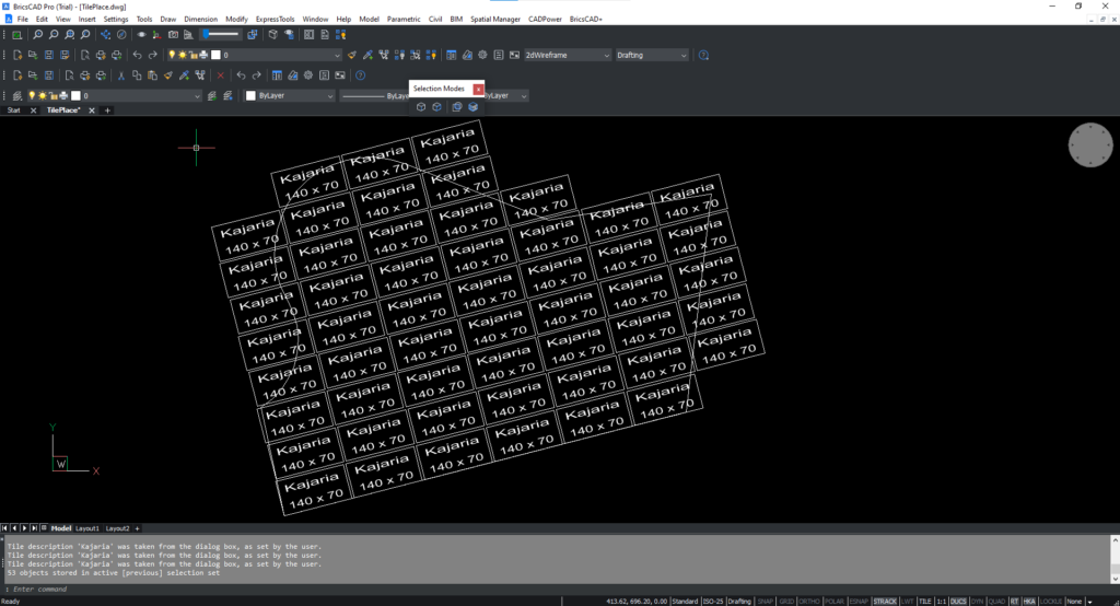
Upon clicking ‘Ok’ and selecting the closed polyline and the base point and direction, you will see that the tiles are placed filling the closed polygon in the manner shown above. This is the default output of the CP_TILEPLACE command.
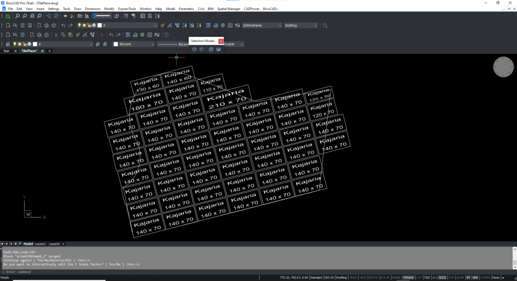
One the default arrangement of the tiles is offered by the CO_TILEPLACE command, the next step would be to interactively edit the scale factors of the tile so that they fit into the space correctly.
The standard tile (in this case 140 x 70 would cover most of the closed polygonal area, but the edge pieces would have to be manually arranged.
This done using the CP_SCLEDIT command which can be found here:
CP_SCLEDIT: CADPower -> Blocks -> Block-related -> Interactive XY Scale Editor 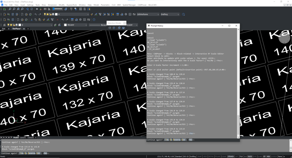
CP_SCLEDIT is a tool to interactively edit the X and Y scale factors of blocks so that you can precisely arrive at the exact dimensions you need. This command works by allowing you to edit independently the X and Y scale factors of the blocks around a specified reference point in such a way that the the desired geometry is obtained.
In this manner, you must edit all the tiles to fit into your space, as per your design.
There are a couple of other tools that can be used to help in this process of tile laying.
One of them is the CP_TILEOFFSET command
CP_TILEOFFSET: CADPower -> BOM/BOQ Tools -> Offset tiles / XY sized panelsYou can use the CP_TILEOFFSET command to quickly offset a tile in the along- or perpendicular- directions. There is also an option to offset an entire row of tiles in one go. This can help in saving precious time while working with large designs.
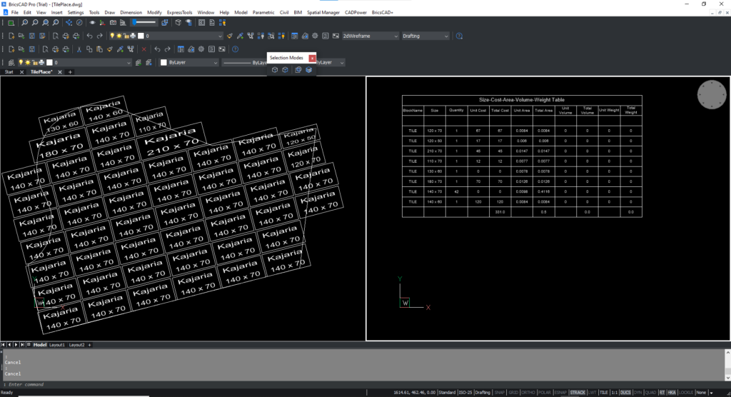
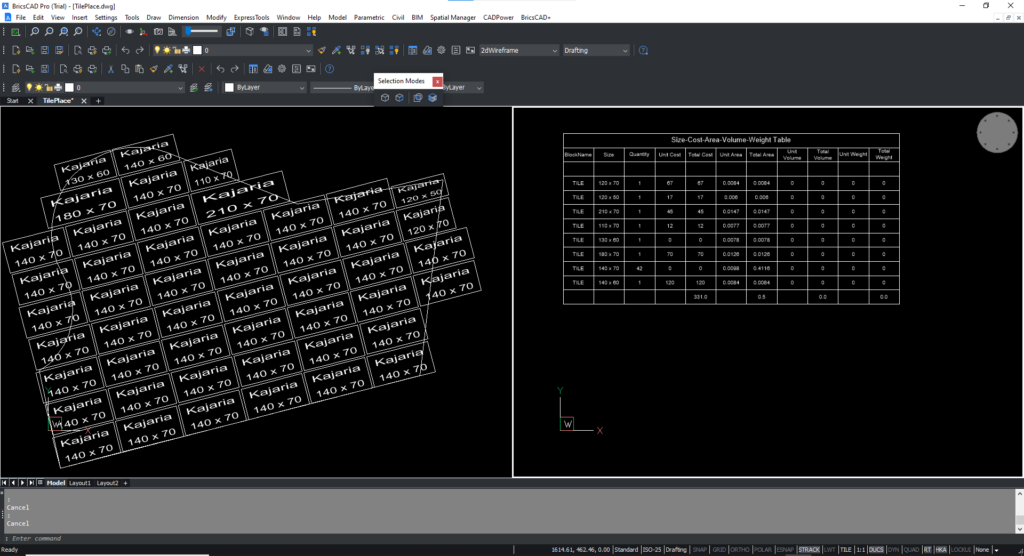
CP_TILECOUNT: CADPower -> BOM/BOQ Tools -> Create Bill of Materials/QuantitiesIn this last step, you can use the CP_TILECOUNT command (or its alias CP_BOM) to count the number of tiles based on the scale factors and create a table showing the cost, quantity, time, area, volume and weight parameters.
All these extended information can be extracted from the design by specifying the information appropriately in the INI files.
This forms a complete workflow where you can fill a closed polygon space with rectangular tiles, optimize the space and edit them interactively, and finally create a quantity takeoff table that provides full cost, time, area and volume statistics.
There are advanced operations also possible in CP_TILEPLACE
If you look at the CP_TILEPLACE dialog box carefully, there are several additional options and features there that we did not discuss in this post.
There is a possibility to define the tile element as 3D. This requires you to input an additional parameter (depth) and it will be used in volume computation.
The volume details will be shown in the created table.
There is also an option to attach additional resources to the tile. Additional resources are peripheral materials like screws, bolts, paint, glue or similar items that may be associated with each tile. You can specify these info in the INI file under the [RESOURCE&MATERIALS_DEFINITION] section and they will be added in the final quantity table.
The tabulated Quantity takeoff summary from CP_TILECOUNT
