
CADPower-GeoTools V24.18 productivity features
CADPower-GeoTools V24.18 productivity features
Improvements in CADPower
CP_QHATCH (CADPower -> Draw -> Symbology -> Quick Hatch (CADPower enhanced)
-and-
(BricsCAD+ -> Quick Hatch)
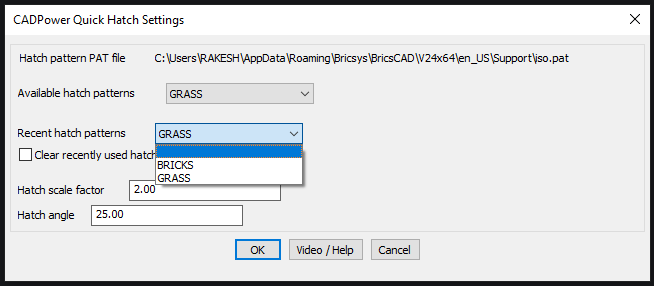
The CP_QHATCH command have been improved. We introduced this command in V 24.15 and have written about it there as well. Click here! You now have two sets of hatch patterns list. The first is a list of available patterns, and below that is a list of recently used patterns. This helps repeated entry easier by making the user only chose through the currently used hatch patterns instead of having to navigate the complete list of available patterns.
Please be aware that the CP_QHATCH command is now operational only in BricsCAD (in V 24.18), and will soon be available in AutoCAD and ZWCAD also.
A unique feature of this command is that it saves each hatch scale and hatch angle in the registry and offers the same as defaults when you chose it. This feature along makes it easier and faster to use than the regular HATCH command. This is very useful for users doing frequent hatches, and having to use multiple patterns.
In addition, the original USP of this command is the ability to quickly select a HATCH pattern from a pull-down menu rather than from a palette.
We would like to remind our BricsCAD users that the command is provided in the BricsCAD+ pull-down menu also.
CP_UPDATESUPPORT (BricsCAD+ -> Support -> Update Hatch patterns and/or fonts)
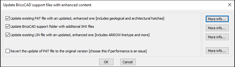
The CP_UPATESUPPORT command have been improved. We introduced this command in V 24.15 and have written about it there as well. Click here! In this update, we have fixed some major bugs and also ensure it runs properly in AutoCAD and ZWCAD.
The user-interface behavior has been improved as well, and it now correctly switches on and off options that logically make sense.
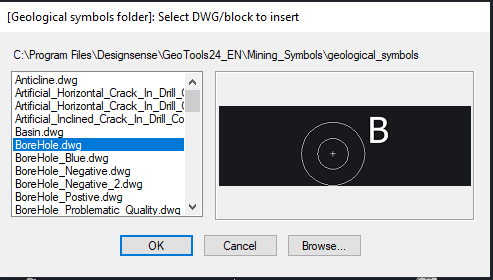
CP_DWGBROWSER (CADPower -> Miscellaneous -> File Management -> DWG Browser, with thumbnail previews)
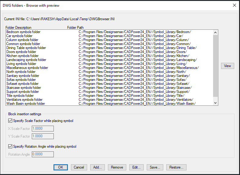
The CP_DWGBROWSER command in CADPower offers a vast collection of open-source symbol libraries that we have collected over the past many years. In this update, we have organized and documented the collection better for easy, error-free access.
In the above dialog box, you can specify the way the symbols will be inserted in the drawing. You can have a fixed scale factor and rotation angle, or you can specify them on the command line.
Please remember to specify the scale factor or rotation explicitly on the command line. Pressing an ENTER causes the command to terminate and no symbol block is placed.
The CP_DWGBROWSER command has been improved and extended. The INI file defaulting procedure has been improved and it no longer creates a blank drawing in AutoCAD when the current drawing is not saved. The number of freeware libraries which we have collected over time has been improved and provided here for your use.
The following categories of symbol libraries have been added:
- Bedroom symbols
- Car symbols
- Column symbols
- Common symbols
- Dining Table symbols
- Doors symbols
- Kitchen symbols
- Landscaping symbols
- Living symbols
- Miscellaneous symbols
- North symbols
- Sanitary symbols
- Sofas symbols
- Sofaset symbols
- Staircase symbols
- Support symbols
- Title symbols
- Ventilators symbols
- Wash Basin symbols
- Windows symbols
The CP_DWGBROWSER command is available in CADPower for BricsCAD also.
CP_LAYERMAN (CADPower -> Layer -> Layer Names Manager)
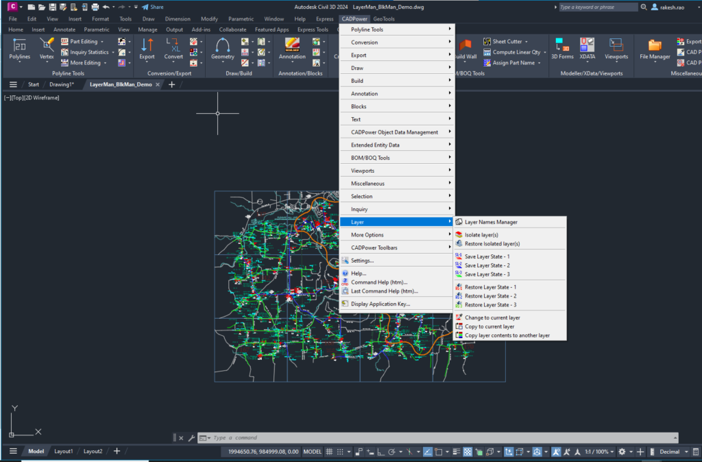
The CP_LAYERMAN command in CADPower is a powerful layer management tool, that can be used to rename layer names in intuitive ways. Apart from rhe usual operations like adding / removing prefixes from layers, trim starting or ending characters, a new workflow option was added in V 24.18 of CADPower which allows layers to be cleaned after an XREF drawing has been inserted using the XBIND command or the Bind option of the XREF command.
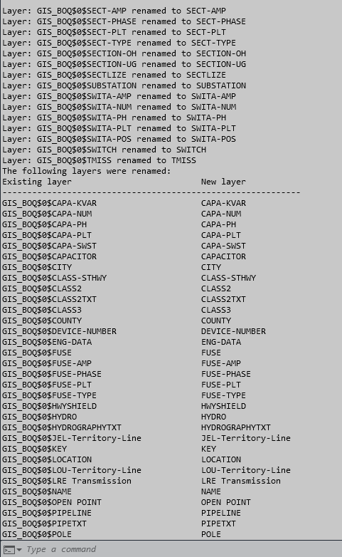
The XREF-Resolve operation renames the layer so that the XREF drawing name in the layer followed by the $0$ is removed, making the layer names more same and readable.
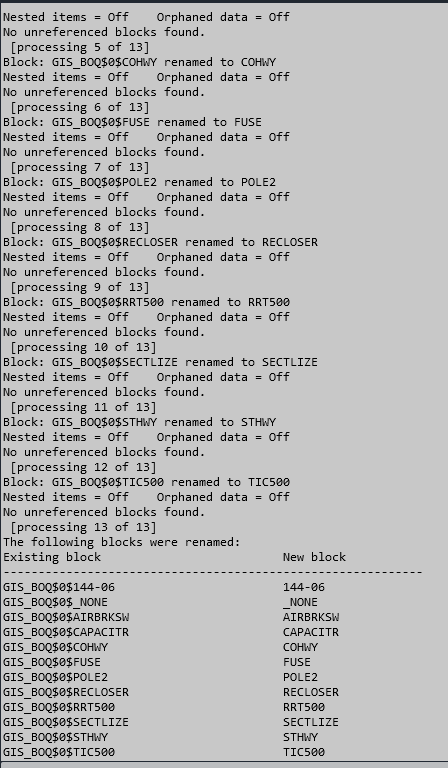
CL_BLKMAN: CADPower -> Blocks -> Block Names Editor
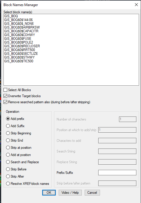
The CP_BLKMAN command is a block names manager tool in CADPower. We have introduced a new option called ‘Resolve XREF-block names’. This is our humble attempt to clean up the hundreds of block names that often get created when XREF files are made part of the current drawing using the XBIND or XREF->BIND option.
When you insert an XREF using the BIND option, the block names in the XREF drawing get renamed with a prefix <xref>$0$, where <xref> is the name of the incoming XREF drawing.
The ‘Resolve-XREF-block names’ option will automatically rename all blocks so that they have meaningful names without the appendage of the incoming XREF block.
Improvements in GeoTools
GEOL_MININGSYMBOLS (GeoTools -> Mining & Geological Tools -> Mining Symbols)
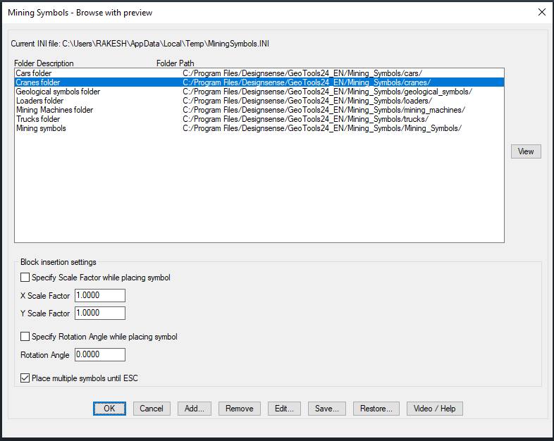
The GEOL_MININGSYMBOLS command is very similar to the CP_DWGBROWSER command of CADPower. In this command, we present to you a vast collection of symbol libraries that are useful for the mining and geological design professionals. These are open-source data and symbols collected over a period of time from various sources. A significant number of the symbols here are contributed by the late Mr. Ivo Cotman from Croatia, a leading geologist and entrepreneur, who was an authority of dimensional stone mining. Mr. Ivan Cotman and his team were power users of GeoTools MIning module from the year 2008 to around 2018, when he passed away. As a tribute to the role played by Mr. Cotman in the development of the Mining and Geological module in GeoTools, we are on a mission to document some his ideas in detail and provide them in GeoTools for our worldwide users at large.
The following categories of symbol libraries have been added:
- Cars
- Cranes
- Geological symbols
- Loaders
- Mining Machines
- Trucks
- Mining symbols
GT_DRAWGISPOLYGON (GeoTools -> Draw -> Draw polygons (for mapping, GIS))
The GT_DRAWGISPOLYGON command in GeoTools has been born. This promises to be a useful tool to create building outline geometry that is often digitized from drone imagery, aerial photos and similar data sources.
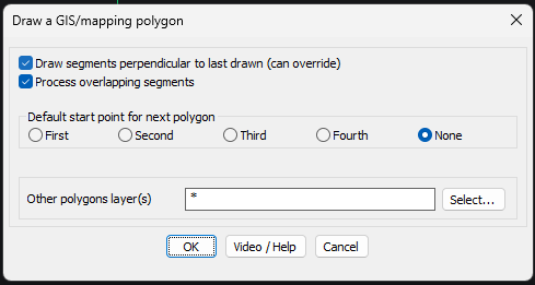
The ‘Settings’ dialog box contains a bunch of parameters that control how the digitization process works.
Drawing segments perpendicular to each other: Digitizing buildings is often done with orthogonal (right-angled) sides. This option can be set, but it can be easily overridden at each point input by simply pressing the F8 (ORTHOMODE) option on or off. When it is on, you can create building geometry easily where the walls of the building are perpendicular to each other.
Processing overlapping segments: When you create a new polygon that intersects an existing polygon, it is normally expected that there is either a union of the two polygons or a subtraction of one (mostly bigger) polygon from the other.
Default start point for the next polygon: When you digitize polygons, you do them one after the other, in succession. When you create the next polygon, where do you want the start point to be set as default? That is what you can control here. Run this command a few times, and you will realize what the First, Second, Third and Fourth points of the polygon are. You can set one of these points as the next default start point.
Other polygon layer(s): This specifies the layer(s) to look for when you are searching for other polygons to merge or intersect.