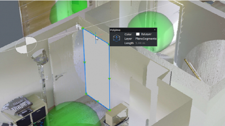
A point cloud is a large set of data points in a 3D space and is generally produced by a 3D laser scanner. The points can represent any shape or object, this can be a construction site, a building, a mechanical part, an art installation, etc. This 3D representation can be used for many output purposes, from quality inspection to rendering animations.
To further improve our point clouds functionalities, we have taken in account user’s feedback and continued to work on performance and usability. Therefore, please take a look at the new point clouds features in BricsCAD V22.
Improvements to the User Interface
Point Clouds commands in the ribbon
In V22 we’ve created a new tab in the ribbon, specifically for point cloud-related functionalities. From here, you can insert and edit your point cloud, without having to type in the commands in the command line.

Point cloud Reference Manager
The brand-new point cloud Reference manager gives you a complete overview of all the pre-processed point clouds on your disk. You can find the Name, Path, Size, Status and Settings of the files and directly insert a point cloud into the current drawing. From this dialog you can also start pre-processing a new point cloud file and check the progress of the import. We support all popular formats like e57, .LAS, .PTS, .PTX, .RCP, .RCS and in V22 also .LAZ. The scan data will be converted to our own data structure and is saved in the Pointcloudcache folder. This pre-processing is a background process and is partly multithreaded.

Improvements on Point Cloud viewing
POINTCLOUDCROPSOLID
POINTCLOUDCROPSOLID is a cropping feature based on a solid geometry, making the crops easier to and edit and move around. You can use this cropsolid like a regular section plane/volume, but you also use cropsolid on a smaller scale as well. An example is for renovation projects, if you want to delete a certain wall, you can do this by drawing a solid box around this wall and use POINTCLOUDCROPSOLID on it to visually hide that part of the point cloud.

Drawing in Bubble View
Last year we introduced the Bubble View, these are the green spheres in the point clous and represent the location of the scanner during the point cloud creation. Bubble Views can be used to navigate through a point cloud and for 2D and 3D creations in a drawing.
In V22 we have enabled full 2D drafting capabilities in the Bubble View. You can do anything drafting related in the Bubble View, like tracing beams or other structural elements, draw steps of a staircase, draw a contour of a façade, etc. Other than drawing lines and polylines, you can use many other commands like DIMENSION, TEXT, INSERT in Bubble View.
POINTCLOUDDEVIATION
To further expand on color mapping functionalities on point clouds, we have added POINTCLOUDDEVIATION to map the deviation between a point cloud and an existing surface or solid. This feature checks the distance between a surface or solid and the points of a point cloud, you can also check this deviation with multiple surfaces and solids at the same time. Depending on the tolerances set in the Command panel, the color of the points might differ, giving you the point deviation fractions within the ‘Accept’, ‘Warning’ and ‘Bad’ tolerance.

Improvements on geometry generation*
*BIM license required for this functionality.
POINTCLOUDFITPLANAR improvements
In V21 we introduced the POINTCLOUDFITPLANAR command, which is a feature to automatically generate 3D geometry. You can use this command in modelspace or in Bubble view. If the Bubbleviewer is open before launching the command, BricsCAD expects you to select the walls/slabs in Bubble View instead of in modelspace.
This creates a surface or solid after a selection of one point of the point cloud. We improved this workflow in V22. The POINTCLOUDFITPLANAR command is now implemented in the Command panel, giving you a better overview of all the different options and settings within the command.
One of the added options is ‘Adjust Borders’, giving you the opportunity to redraw and adjust the border of the generated surface. Another new option is to automatically ‘Select Opening’, this will create a polyline according to the contour of the opening, for example windows and doors.

With POINTCLOUDFITPLANAR, we also improved on the connection between the generated surfaces. When selecting surfaces in Bubble View, you can SHIFT + click on adjacent intersecting planes to automatically connect these surfaces.

Lastly, we have added the option to create Space solids from the detected wall surfaces. When SHIFT + clicking on the adjacent walls and slabs with the option ‘Stitch surfaces’ ON, BricsCAD will automatically stitch the detected surfaces together to create a solid. This solid can represent the Space and/or volume of the detected room.

POINTCLOUDFITCYLINDER
To further build on automatic geometry detection, we have added the POINTCLOUDFITCYLINDER command. Instead of fitting planar surfaces and solids, this command will automatically detect cylinders in a point cloud, for example, columns and piping.

We hope that this have given you an exciting insight into the developments and improvements for Point Clouds in V22! Are you interested in learning more about point clouds in BricsCAD?
But that’s not all that’s new for BricsCAD® V22!
There’a a whole host of great new functionalities that will transform your workflows and productivity! To see everything that’s new for BricsCAD® V22, be sure to and come back to the blog, as we will be exploring more features soon!
Blog Credit:

