Connecting Block Attributes, Auto-Poly-Detect Labeling and More: CADPower-GeoTools V 17.11 Update
Bengaluru, India

CADPower V 17.11 Update
New command added: CP_AUTOPOLYLABEL (Menu: CADPower -> Annotation -> Automatic Polygon Detect & Label):
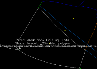
The CP_AUTOPOLYLABEL command is an automatic polygon detect, shape detect and area labeling command rolled into one.
It runs entirely on the command line and asks the user several questions like polygon edge layer(s), closed polygon and label layers, text height, polygon name and so on.
The command applies the BOUNDARY command around the picked point to identify the enclosing polygon.
The user is given a choice whether to create the actual closed polygon or just report its area and shape in the MTEXT object created.
The resulting polygon geometry is also described as a shape (rectangle, square, circle or polygon with n sides).
While annotating areas, it is also possible to optionally acquire the area annotation and conversion parameters as set by the CP_CALCAREA command and use the same in this annotation as well.
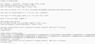
The command-line user interface to input detailed parameters
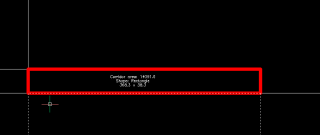
A rectangle automatically detected around the picked point, and annotated with dimensions
Enhanced command: CP_CONNECTBLOCKS (Menu: CADPower -> Blocks -> Block Related -> Connect blocks based on attribute values):
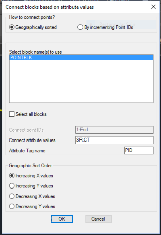
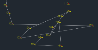
The CP_CONNECTBLOCKS command connects blocks based on attribute values. The command has been reworked completely and is as good as new now.
You can specify one of more block names, an attribute tag and a connect criteria.
All blocks whose attributes match the specified criteria will be joined by a single polyline.
The ‘Connect criteria’ is specified in two ways:
Geographically Sorted: Checking this option sorts matching attributes purely based on a geographi sort order. The following geographic sort orders are supported:
- Increasing X values
- Increasing Y values
- Decreasing X values
- Decreasing Y values
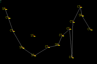
By incrementing Point IDs: Checking this option sorts matching attributes purely based on the increasing order of their attribute values, and not geographically.
The values can be entered as follows: 1-50,60,90-End
The above syntax would connect points from 1 to 50, then 60, followed by 90 to the end (maximum) point number in the drawing.
Two special values permitted in the syntax are ‘Start’ and ‘End’ which would use the minimum and maximum point number respectively in the drawing.
Bug fixes: The loading of the partial CUI menu in BricsCAD has been improved and some errors which were observed while running the German version has been fixed.
*** New CADPower videos
Create centroid marks inside closed polygons
Connect blocks based on attribute values
*** New GeoTools videos
Create centroid marks inside closed polygons
Create closed polylines from a mass of networked polylines
Google Earth Rubber Sheeting Tool
DWG2KML Google Earth KML/Z Export
Draw cross-sectional profile from 3D polyline
