GeoTools-CADPower V 20.05, We have Invaded Civil 3D, and AutoCAD Map, Data Location Changes
Bengaluru, India

We are pleased to announce to you the release of V 20.05 of GeoTools and CADPower today which is a major update that delivers a new way of design in GeoTools.
The CADPower Object Table Data (also available in GeoTools) functions were announced in V 20.03 and we spent the past few weeks bug-fixing and improving the tools with user feedback.
These set of tools mimic the object data functions of AutoCAD Map, and forms the database backbone to many of the GeoTools and CADPower functions.
We list again the Object Data Functions in GeoTools & CADPower (available in V 20.05).
(new command) CP_DATAMAN / GT_DATAMAN:
CP_DATAMAN @ CADPower -> Build -> CADPower Object Data -> Data Manager
GT_DATAMAN @ GeoTools -> Build -> GeoTools Object Data -> Data Manager
This command is brand new and offers all tools for object table definition creation & editing.
Here, you can create a new object data table, add fields and specify their types and set default values.
The user interface of this command is simple and self-descriptive.
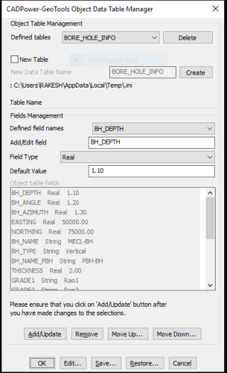
The following object data field types are support : Integer, Real and String.
In the upcoming updates, two more field types: Point and (hyper)Link-URL will be supported.
The Object Table Data is stored in two places: as part of the drawing (embedded within) and in external INI files.
Within the drawing, the data is stored in dictionaries while the INI file is by default created and stored in the User/AppData folder.
A sample INI file looks something like this:
[*RECORD]
NAME=LANDINFO
Type=XDATA
FIELD=PARCEL_NAME,String,-
FIELD=AREA,Real,0.0000
FIELD=YEAR,Integer,2019
FIELD=POPULATION,Integer,0
[*RECORD_END]
The end-user never needs to know the INI format, it is shown here just for the geeks and if you want to know how to interpret and fix the file (if required).
(new command) CP_ATTACHDATA / GT_ATTACHDATA:
CP_ATTACHDATA @ CADPower -> Build -> CADPower Object Data -> Attach Data
GT_ATTACHDATA @ GeoTools -> Build -> GeoTools Object Data -> Attach Data
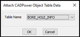
This command allows object data tables to be attached to selected entities. The default values for the fields as specified during the table creation will be copied and set during this process.
(new command) CP_DETACHDATA / GT_DETACHDATA:
CP_DETACHDATA @ CADPower -> Build -> CADPower Object Data -> Detach Data
GT_DETACHDATA @ GeoTools -> Build -> GeoTools Object Data -> Detach Data
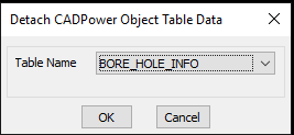
This command allows object data tables to be detached from selected entities.
(new command) CP_EDITDATA / GT_EDITDATA:
CP_EDITDATA @ CADPower -> Build -> CADPower Object Data -> Edit Data
GT_EDITDATA @ GeoTools -> Build -> GeoTools Object Data -> Edit Data
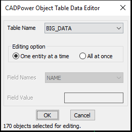
This command allows object data to be edited. If multiple objects are selected, you are presented with the above dialog box and you can edit the object data in two ways:
One entity at a time: Clicking this option brings up the object data editor for each entity separately and you can edit the values manually.
All at once: Clicking this option allows you to set a specified object data value and the same will be applied to all selected entities.
CP_CPOD_EXPORT / GT_CPOD_EXPORT:
CP_CPOD_EXPORT @ CADPower -> Build -> CADPower Object Data -> Export Data
GT_CPOD_EXPORT @ GeoTools -> Build -> GeoTools Object Data -> Export Data
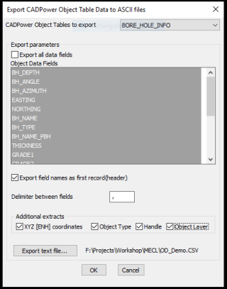
The CP_CPOD_EXPORT command allows to export the selected fields of an object table data to a CSV file. The delimiter in the file can be specified and additional exports like XYZ coordinates, object type, handle and object layer can be exported as well.
In the next version, we will include the ability to import the data exported by CP_CPOD_EXPORT and update the data inside the CAD platform.
This will function on similar lines of the ATTIN / ATTOUT command of AutoCAD but here, it applies to just about any entity.
The ability to attach data to entities is far-reaching and many existing CADPower and GeoTools command have started to take advantage of the same.
CP_CPOD_IMPORT / GT_CPOD_IMPORT:
CP_CPOD_EXPORT @ CADPower -> Build -> CADPower Object Data -> Import Data
GT_CPOD_EXPORT @ GeoTools -> Build -> GeoTools Object Data -> Import Data
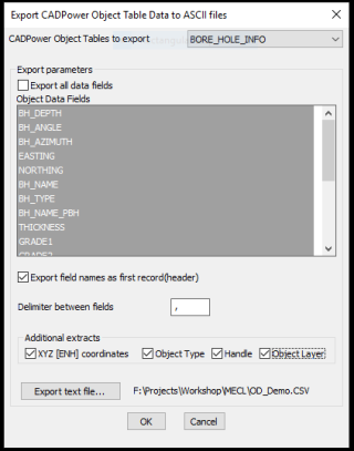
The CP_CPOD_IMPORT command allows importing of an object table data CSV file (which was previously exported with CP_CPOD_EXPORT).
The incoming CSV file must have the Handle field in order for the data to be imported and updated in the CAD drawing.
GeoTools V 20.05 Update – Major New Push into Civil Tools
In other big update of features, we have invaded into the terrain of many Civil 3D-like functions and made it available in GeoTools in a much seamless manner.
(new command) GT_IMPORTSURFACE (GT_IMPORTSURFACE @ GeoTools -> Civil Tools -> Import TIN Surface Data):
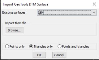
The GT_IMPORTSURFACE command is used to import a previously saved GeoDTM TIN data.
GeoTools TIN data is saved in external .GeoDTM files using the GT_EXPORTSURFACE command and the same can be retrieved here.
By default, the .GeoDTM files are saved in the <user/AppData/Local…GeoTools> folder, and their list is shown in the drop-down menu.
You can also import the Surface from a .GeoDTM file stored elsewhere on your computer. Use the Browse button to select such a file.
While importing, you can specify whether you want to import the points, TIN triangles or bot. At the end, it reports the number of points or triangles imported.
The rectangular boundary of the surface also is imported as a closed 2d polyline.
(new command) GT_EXPORTSURFACE (GT_EXPORTSURFACE @ GeoTools -> Civil Tools -> Export TIN Surface Data)
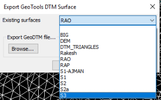
The GT_EXPORTSURFACE command is used to export a selection of 3d polylines or 3dfaces into .GeoDTM TIN data files, stored externally.
By default, the .GeoDTM files are saved in the <user/AppData/Local…GeoTools> folder.
A ‘Browse’ button is also provided to enable you to save the surface in a different location. In such case, two copies of the surface is saved, one in the default AppData folder and another in user-specified location.
(updated command) GT_PTINTERAUTOMATIC (GT_PTINTERAUTOMATIC @ GeoTools -> Civil Tools -> Interpolate point elevations from surfaces)
The GT_PTINTERAUTOMATIC command is useful to assign point elevations by interpolating the elevations of neighboring polylines or 3dfaces from surface data.
This is done by automatically scanning the surface data layers.
You are first asked for an initial zoom window size. If surface data for interpolation could not be found in the specified zoom, the value is incremented by 1.0 unit and a new search is initiated.
Next, you must specify the surface name to be used. A list of available saved surfaces are presented.
The surface data must also be available in the drawing in the layer Surface_<Surface_Name>. If such data is not available, it must first be imported using the GT_IMPORTSURFACE command.
You can get the surface elevation at the picked point or select a number of existing points (or blocks) and have their elevations updated by interpolation.
(new-renamed) GT_ALIGNMENTCF (GT_ALIGNMENTCF @ GeoTools -> Civil Tools -> Alignment Cut/Fill)
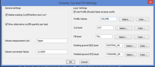
The GT_ALIGNMENTCF command is used to analyze two cross-sectional profiles created by GT_CROSSSECT command and compute the cut-fill areas across the profile.
The inputs for this command are the closed cross-sectional profile line created by GT_CROSSSECT command and a new finished grade alignment line across the profile that you want to place.
Given these two inputs, the GT_VOLUME command will compute the cut and fill areas and color them accordingly as specified in the settings (see dialog box above) and display the same on the profile.
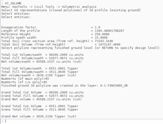
The volume computation can be reported in terms of number of cubic units or as a measure of the number of excavating vehicles.
For example, if I have a tipper capable of carrying 12 cu.m of soil, I will enter the ‘Volume measurement unit’ as ‘Tipper’ and the ‘Volume Conversion factor’ as 12.0.
![]()
The GT_ALIGNMENTCF command can also create an updated 3d polyline that represents the finished ground level.Since the existing ground profile is linked to the 3d polyline from which it was created, GT_ALIGNMENTCF command creates an updated 3d polyline of finished ground polyline as well.
The layers for existing ground and finished ground are specified in the dialog box as shown above.
At the end of the computation, there is also a listing of the total area of fill and cut.
(new-renamed) GT_SURFACEVOLUME (GT_SURFACEVOLUME @ GeoTools -> Civil Tools -> Compute Surface Cut/Fill Volumes)
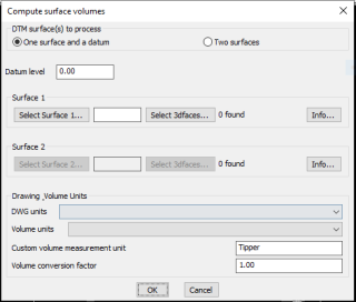
The GT_SURFACEVOLUME command is used find the volume between two surfaces, or between one surface and one datum reference elevation.
You must specify the surfaces from the list. They must be saved surfaces and must be imported into the drawing as well.
The command computes the volume of the surfaces and reports them in drawing units.
This is a work-in-progress command and in the next update, it is planned to have the ability to present the volumes in different units.
For example, you can specify the drawing unit and the volume unit and the system will do an automatic conversion and present the volume quantities accordingly.
(updated command) GT_DRAPEPOLY (GT_DRAPEPOLY @ GeoTools -> Build Tools -> Drape a polyline across a set of intersecting objects)
The GT_DRAPEPOLY command can be used to drape a set of 3d polylines (source objects) over a set of intersecting linear objects (target objects).
Upon draping, this command creates vertices all along the source objects (3d polylines) where they intersect the target linear objects.
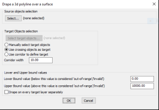
The dialog box above allows entry of various controlling parameters.
You can specify ‘Out-of-Range’ values if you know the valid elevation limits of your data so that you can eliminate erroneous processing.
Selection of source objects is by a usual selection method. Selection of target objects can either be manual or by crossing or by a defined corridor.
For source objects, lines and polylines are the allowed selection objects.
For target objects, the acceptable objects for selection are lines, polylines, arcs, splines and 3dfaces.
The addition of the dialog box is a significant improvement to the usability of this command in V 20.05
(new) CP_ACTIVATELICENSE (CP_ACTIVATELICENSE @ CADPower -> More Options -> Activate CADPower License)
The CP_ACTIVATELICENSE command is new in V 20.05 and provides an easier method to activate your CADPower license. Upon starting this command, you will be prompted to select the CADPower??????.RGS file and the license is activated on the computer.
The file will be copied to the Users/AppData folder. For example, on my computer this folder would be:
c:\Users\RAKESH\AppData\Local\CADPower\BricsCAD\V20 for BricsCAD c:\Users\RAKESH\AppData\Local\CADPower\AutoCAD\V20 for AutoCAD.
Upon re-starting your CAD application, the license will be automatically read and recognized.
(new command) GT_ACTIVATELICENSE (GT_ACTIVATELICENSE @ GeoTools -> More Options -> Activate GeoTools License)
The GT_ACTIVATELICENSE command is new in V 20.05 and provides an easier method to activate your GeoTools license. Upon starting this command, you will be prompted to select the GeoTools??????.RGS file and the license is activated on the computer. The file will be copied to the Users/AppData folder. For example, on my computer this folder would be c:\Users\RAKESH\AppData\Local\GeoTools\BricsCAD\V20 for BricsCAD and c:\Users\RAKESH\AppData\Local\GeoTools\AutoCAD\V20 for AutoCAD.
Upon re-starting your CAD application, the license will be automatically read and recognized.
(new) Other changes in licensing and storing of CUI/MNU/dll/bmp files
GeoTools and CADPower use CUI & MNU files to define their user-interface. Additionally, dll and bmp files are used to define the icons used by the various toolbars. Until now, these were saved in the installation folder, which by default was in the “c:\Program Files\DesignSense\” folder.
The downside of this was that most users cannot make a change to the files in this folder due to Windows permission issues. With a growing number of our users wanting to further customize the user-interface or define their own shortcuts and macros, this was becoming a difficult issue to handle.
To overcome this, we now copy and store the UI files in UserLocalAppData folder whose path is similar to this example:
c:\Users\<user_name>\AppData\Local\<productname>\<platform>\<version>
<user_name> – your Windows user name
<productname> – is either GeoTools or CADPower
<platform> – is either BricsCAD or AutoCAD
<version> – is the current version number of the product
CADPower V20 for BricsCAD: EXE (-or-) ZIP (Linux/Mac compatible)
CADPower V20 for AutoCAD: EXE (-or-) ZIP
GeoTools V20 for BricsCAD: EXE (-or-) ZIP (Linux/Mac compatible)
GeoTools V20 for AutoCAD: EXE (-or-) ZIP
BricsCAD V19: Trial download
BricsCAD V19 Shape: Free download
BricsCAD Communicator V19: Trial download
Key Contacts: rakesh.rao(at)thedesignsense.com / +91-9243438300 / +91-8073279755
Follow us on Twitter: https://www.twitter.com/rakesh_rao
Key Contacts: rakesh.rao(at)thedesignsense.com / +91-9243438300 / +91-8073279755
Follow us on Twitter: https://www.twitter.com/rakesh_rao
