

In this blog, let’s talk about the GeoTools-CADPower V26.14 update.
Since the release of the V26 version of GeoTools and CADPower in October 2025, we ave made several improvements and bug fixes.
Today, we are pleased to announce to you, version 26.14 of our popular productivity plugins that adds several useful improvements.
Read further for a quick summary!
New right-click option to change dimension units in BricsCAD
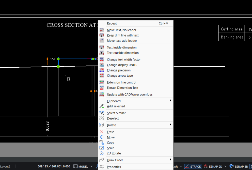
CADPower now offers a quick tool to change the display units in the selected dimensions.
This has been one of the most frequently asked questions during BricsCAD demos, and the workaround we have been giving until now is to enable alternate dimension units. The downside to this is that it eats up precious space on your drawings and can possibly clutter your data. Further, alternate dimension units only can switch between feet and inches vs a metric measurement. The CADPower implementation allows complete units control, which is a great convenience.
This tool is enabled both as a context-menu which works on selected dimensions (by right-clicking on them) and as a standalone command called CP_DIM-UNITCONV.
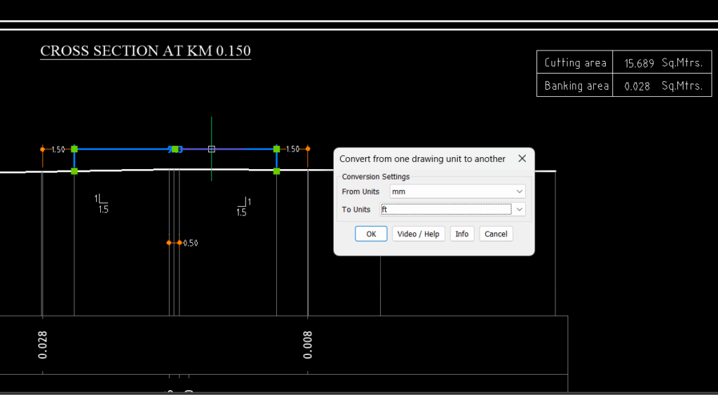
You need to select the ‘From’ units and ‘To’ units in the dialog box. The source dimensions are converted only for display. The underlying geometry or the locations of the dimensions themselves are not changed.
This is a quick way for you to change the dimensions to a unit you are more familiar with. Its best use case is perhaps when you receive this drawing from a consultant or client which may have been created in a different unit.
New command added: CP_POLYDIM
CADPower -> Miscellaneous -> CAD Procedures -> Second Set -> Smart Dimensioning along polyline
The newly added CP_POLYDIM command is used to automatically create dimensions on polyline vertices based on numbered vertex specification and offset distance.
This tool works best when you have a number of polylines of the same type (usually created by automated program), and you want to create dimensions around selected vertices in a specific order.
As an example, we show in this image a polyline representing the canal cross-section and you need to create the dimensions as shown.
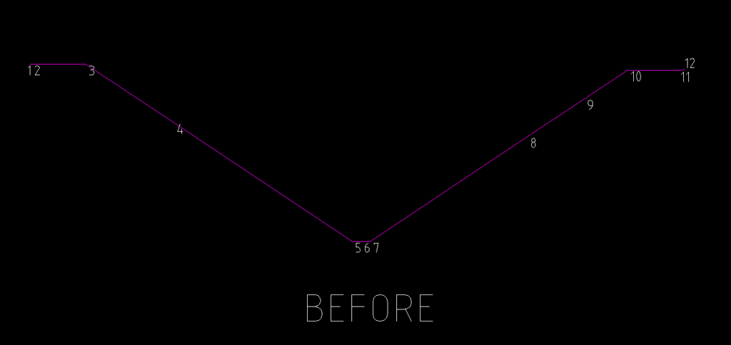
In the above example, you can see the canal cross-section drawn as an open polyline. The vertex numbers are shown. Based on this, we need to create a dimension near the segments formed by vertices, 2-3, 5-7, 10-11 and 3-10.
You will need to specify to the program by building a sequence string which looks like this:
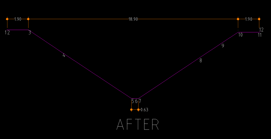
2-3@5.00, 3-10@5.00, 10-11@5.00, $5-7@m5.00
Each segment dimension is separated by a comma (,) character.
The 2-3@5.00 indicates that the start vertex is 2 and end vertex is 3. The @ sign specifies the offset identifier and 5.00 means an offset of 5.00 in the vertical up direction.
If there is a $ character in front of the start vertex, it indicates the offset to be measured from the Y level of the segment start point, else the offset will be measured by default from the Y level of the polyline start point.
If there is an m character, like in $5-7@m5.00, this is used to denote a negative (or minus) offset. The dimension offset will be in the vertical-down direction instead of the vertical-up direction.
Using this syntax, you can build most of the commonly required dimensioning syntaxes based on vertex pairs and offset distances and direction.
This works best when you have a set of polylines with a predictable and fixed vertex structure.
Enhanced command: CP_ATTACHURL
CADPower -> Miscellaneous -> CAD Procedures -> Second Set -> Attach URL to objects
The CP_ATTACHURL command has been significantly udated and new options added to link images who name exists as AutoCAD Map Object table data, CADPower object table data or block attributes.
In addition, it is also possible to enter the file name manually like before.
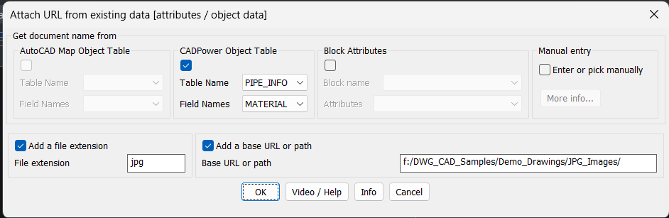
In the above example, you can see that the object data is taken from the CADPower Object table name called PIPE_INFO, and from a field called MATERIAL. The field MATERIAL contains the material name which is material_1, material_2, material_3 and so on, and it is available as JPG files on the hard-drive as specified.
It can even be on a URL and that can be specified in the section called ‘Base URL or path’.
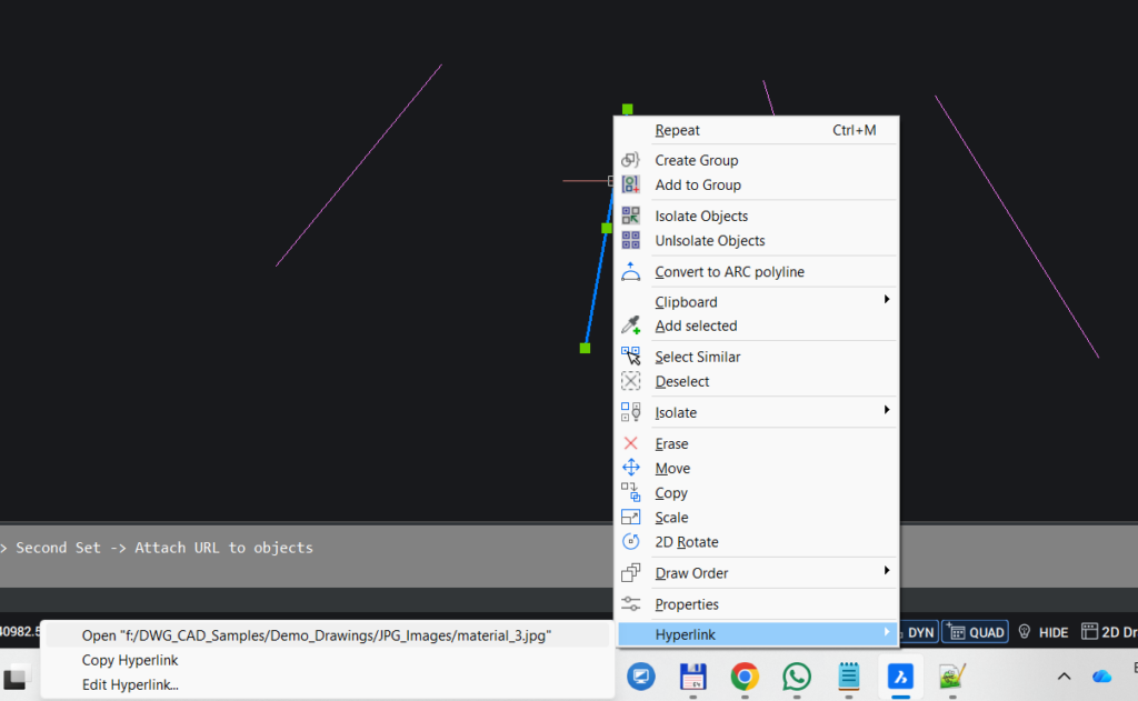
In a similar manner, you can link dynamic data from block attributes or AutoCAD Map Object table data to your linked URL. Once linked using this tool, it will be available to open when you right-click on the entity.
Enhanced command: CP_EDITDATA
CADPower -> CADPower Object Data Management -> Edit Object Data
We have improved the performance of the CP_EDITDATA. If you change the object table data structure (i.e added new fields, for example) after you have created it, it is now possible to show the newly added fields in the edit dialog box.
In other words, you can now add new fields to your table and edit the new fields using this tool. Until now, it would only show the existing fields, and not the new ones added.
Enhanced command: CP_SPORTEDPOLY / GT_SORTEDPOLY
CADPower -> Draw -> Rule-Based -> Draw a polyline by joining points in sorted order
GeoTools -> Draw -> Draw a polyline by joining points in sorted order
The CP_SORTEDPOLY command in CADPower and its twin GT_SORTEDPOLY command in GeoTools is loved by users from across all design domains.
Whether you are an architect, a civil engineer, a surveyor or a manufacturing specialist, all have had some use of the other for this command.
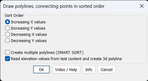
We have now added an option to join text objects, and also read the text values and assign them as as elevations to the created points in the polyline. This eliminates the need to run several GeoTools commands in sequence to achieve the same end result.
You now have the GT_SORTEDPOLY command doing everything for you, and finally create 3d polylines.
One Tool, Four platforms!
GeoTools and CADPower runs on AutoCAD, BricsCAD, ZWCAD and ARES Commander.
You choose your platform. We provide the tools for your automation!
Our preferred, recommended platform is BricsCAD!