Latest update on GeoTools-CADPower V 21.24 – 21.29: New and more features
Bengaluru, India

The past 6 weeks has been extremely busy and productive for us. We released 6 back-to-back updates of GeoTools and CADPower (21.24, 21.25, 21.26, 21.27, 21.28 and 21.29) in an intense development sprint, engaging actual client users.
This post summarizes the same.
GeoTools Updates
A majority of our efforts in the past 6 updates have been focused on the Civil and Mining / Geological Tools.
(Enhancement) GT_CONTOURBUILDER: Menu: GeoTools -> Civil Tools -> Create contours from TIN model :
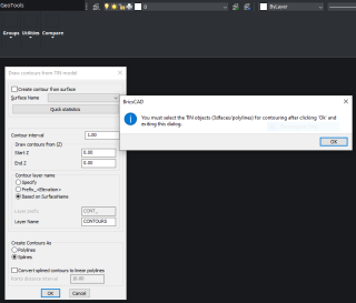
The GT_CONTOURBUILDER command is used to create contours from a set of 3dpolylines or 3dfaces.
You can either specify a GeoDTM surface and use all the TIN data found in the specified layer or select manually from the drawing. In a minor but useful enhancement, this update now allows manual selections to be made from specified layers, in addition to being able to select on the screen.
Additionally, you will now see a message appearing when you uncheck the ‘Create contour from surface’ option which tells you that the manual selection is going to happen once you click ‘Ok’ and exit the dialog box. Better communication!
(Enhancement) GT_SPL2PL: Menu: GeoTools -> Conversion -> Convert Splines to polylines:
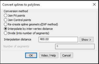
In yet another minor but useful enhancement, a Show option has been added in the GT_SPL2PL command to enable users to show the interpolation distance visually on the screen by picking two points.
This is handy when you would rather point and click and show the distance rather than actually type it out in the box.
(Enhancement) GT_DRAPEPOLY: Menu: GeoTools -> Build -> Drape a 3D polyline across a set of intersecting linear objects:
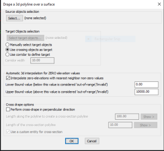 GT_DRAPEPOLY dialog box
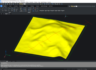 GT_DRAPEPOLY with CROSS-DRAPE applied
The GT_DRAPEPOLY command is used to perform interpolation along a polyline and extract elevations from intersecting 3d polylines and 3dfaces along the way.
This allows polylines to acquire elevations from underlying DEM data and generate a 3d polyline effortlessly.
The GT_DRAPEPOLY command has been significantly enhanced. It is now possible to do a cross-drape also.
When the Cross-Drape option is selected, perpendicular lines will be drawn along the draped polyline at regular specified intervals, and the resulting perpendicular polylines will also get draped into the underlying DEM.
With this option, it is now easy to create a combination of L-sections and cross-sections along it. This can be useful in many roadway alignment projects, irrigation channel design workflows etc.
(enhancement) GT_CROSSSECT: GeoTools -> Civil Tools -> Multiple Cross Section Tools:
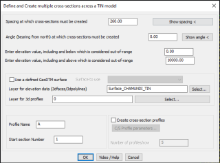
GT_CROSSSECT parameters
The GT_CROSSSECT command is a multi-purpose tool to fill a closed polygonal area with a set of equally spaced lines, do a drape operation on these on the underlying DEM data and then, optionally, also create a cross-sectional profile.
Effectively, the GT_CROSSECT command is a longitudinal section planner, with GT_DRAPEPOLY and GT_PROFILE commands also added inside them.
Among enhancements, the program now displays information messages in a better way during the program run. This enables users to know and take remedial actions for setting up the parameters appropriately.
The ability to create cross-sectional profiles has been made optional.
If you select this option, you are now also able to access the full set of profile creation parameters (as shown by GT_PROFILE command).
Both these improvements now allow the user to have better control on the profile being generated, and importantly, also offers the option to not generate the profile at all.
This is of particular importance when working with large data-sets.
(new command): GT_STRATABUILDER: Menu: GeoTools -> Mining & Geological Tools -> Build bore-hole strata [LITHOLOGY] in different ways
This command connects the user to a set of three new commands exclusively for the purpose of creating cross-sectional lithological plots from bore-hole data.

As the brief description shows, you have three suggested data formats for the lithology data captured from geological exploration.
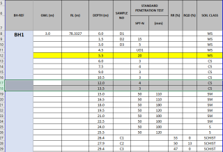
- Bore-hole data is [column-wise], with [cumulative depths], and SPT values [BLOCKs representation]
In this format, the CSV file is expected to have [bore-hole name], [cumulative depth] values, [SoilClass-Lithology] as *MANDATORY* values arranged row-wise.
The block names for each soil classification is defined as per the soil classification.
For example, PEAT block is defined as three blocks: PEAT, PEAT1 and PEATp5 with defined thicknesses of 1.5, 1.0 and 0.5 units. respectively.
All depth measurements are composed using a combination of these blocks and the remaining distance is achieved by scaling the last block used.
Other values like [SPT-N] and [SPT distance], [RR(%)] and [RQD(%)] are not mandatory and used only if specified and available.
The order of any of these parameters in the CSV file is not important and can be specified during the program run.
An example of how the CSV input data may look like is shown below:
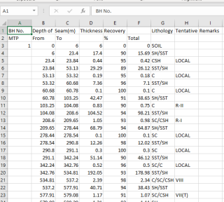
- Bore-hole data is [row-wise], with [From-To-Litho] info [HATCH representation]
In this format, the CSV file is expected to have [bore-hole name], [From-depth], [To-depth] and [SoilClass-Lithology] as *MANDATORY* values arranged row-wise
The strata [lithology] is depicted using HATCH patterns, which must be specified in a separate INI file called the Strata Presentation parameters INI file.
The order of any of these parameters in the CSV file is not important and can be specified during the program run
An example of how the CSV input data may look like is shown below:
- Bore-hole data is [column-wise], with [dip-strike], and strata depths [linear representation]
In this format, the lithological classification is not shown, but the strike and dip directions are drawn in the drawing in 3D
the required values here are [Borehole Number], [Easting], [Northing], [RL-Elevation], [Dip-Angle], [Strike-Angle], [Dirlled Length]
The bore-hole drilled length is depicted using a normal 3d polyline.
An example of how the CSV input data may look like is shown below:
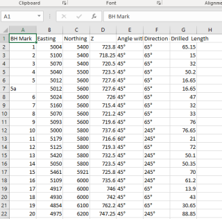
Starting GeoTools V 21.29, we have also included with the build, a sample CSV file for each one of the above case, a sample INI file and an updated, extended PAT file which contains several additional hatch patters of use for the geological and mining industry.
These can be found in the installation folder under the SUPPORT sub-folder.
I will now explain each one of the three methods in detail:
The BLOCKs method
If you wish to use this method, first make sure you have your CSV data in the format shown above.
The column positions are not important and can be specified in the program. The important point is that all the mandatory data must be present in the columns as shown.
Upon clicking this option, another dialog box appears which allows you to specify the detailed parameters as shown below:
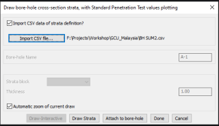 GEOL_STRATABUILDER command – Representing the lithology using BLOCKS
Here, you need to specify the CSV file which has your bore-hole data and then click on the ‘Draw Strata’ button to start importin the CSV data into your drawing.
Before the import can start, you need to specify the columns where each one of the data is available.
This is done on the command line and the transcript is shown below. Please note that if any of the values is not available, there is an option to enter 0 if not present.
If it is a mandatory field, you need to compulsorily enter the value.
Enter [BH data] starting row number in Excel-CSV (required) <8>:
Enter [Depth value] column number (required) <3>:
Enter [Sample Name] column number (0 if not present) <4>:
Enter [SPT-N value] column number (0 if not present) <5>:
Enter [SPT-N distance] column number (0 if not present) <0>:
Enter [Soil classification] column number (required) <42>:
Enter [Bore-hole name] column number (required) <1>:
Enter [RR %] column number (or 0 if not present) <8>:
Enter [RQD %] column number (or 0 if not present) <9>:
Show RR & RQD % values [ Yes/No ] <Yes>:
Enter [Ground water level] column number (or 0 if not present) <0>:
Enter [Reduced Level of surface] column number (or 0 if not present) <0>:
Please make sure the column numbers are specified correctly else the program can crash and leave you with an unexplained error.
The output from this program is a plot of the lithology as shown below:
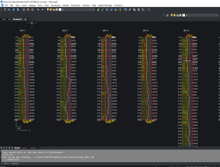 The output from GEOL_STRATABUILDER – Blocks based approach
GeoTools come pre-supplied with a number of popular minerals. If you need to add your own minerals, it is easy and you just need to make three blocks for each mineral, each with thickness of 1.5, 1.0 and 0.5 and name them in the format XX, XX1 and XXp5 where XX denotes the name of the mineral (or lithology strata).
If your drawing does not (yet) contain the desired mineral block, GeoTools will replace such missing lithology with a generic block called GENERIC_MINERAL_BLOCK.
The following mineral blocks are pre-supplied with GeoTools:
- “GENERIC_MINERAL_BLOCK”
- “BLANK”
- “BOULDER”
- “C PEAT”
- “C ROOT”
- “C WOOD”
- “CAVITY”
- “CG”
- “CM”
- “CR”
- “CS WOOD”
- “CS”
- “CWOOD”
- “G WOOD”
- “G”
- “C”
- “GC”
- “GM”
- “GNIESS”
- “GR”
- “LIMESTONE”
- “M”
- “MARBLE”
- “MC”
- “MG”
- “MS WOOD”
- “MS”
- “NR”
- “PEAT”
- “PHYLLITE”
- “QUARTZITE”
- “RUBBISH”
- “S PEAT”
- “S”
- “SANDSTONE”
- “SC WOOD”
- “SC”
- “SCHIST”
- “SG”
- “SHS”
- “SILTSTONE”
- “SLATE”
- “SM WOOD”
- “SM”
- “SS”
- “WB”
- “WOOD”
The HATCH method
in the HATCH method, we use HATCH patterns to represent each lithology strata. The dialog box for input parameters look like the one shown below:
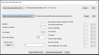
GEOL_STRATABUILDER command – Representing the lithology using HATCH patterns
You will need two input files – the CSV file containing the strata definition and the strata presentation parameters file (INI file).
The strata definition file contains parameters like Borehole name[required], Lithology [required], From [depth.required], To[ depth,required]. Optional parameters include the Recovery[%] and Recovery [Total].
The strata parameters presentation file defines the hatch patterns that each lithology pattern must use, its scale and rotation angle. It is an INI file which looks like this:
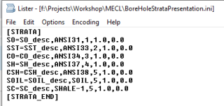
You will need to create the INI file in this format or use the sample provided in the SUPPORT sub-folder and modify it.
There is also a ‘Create’ button provided in the program to help you create a template blank INI file which you can then modify with the correct values.
The column values for the various parameters being read are defaulted as per the CSV data in the sample provided. You will need to change it as per your data.
Please study your data carefully and set the column positions correctly as this is critical to getting correct results.
You can also specify the row number from which you need to start reading the data.
This is important as it helps to skip any header and non-relevant data which may be present at the start of the CSV file.
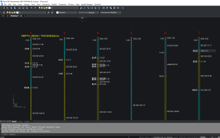
The output from GEOL_STRATABUILDER – HATCH-based approach
You will notice in both the above methods that there is an option to draw the lithology and to attach the lithology data to existing bore-holes.
In both the HATCH approach method and the BLOCKS approach method, there is also an option in the dialog box to attach the lithology information to the blocks as extended entity data.
You can do this by clicking on the option ‘Attach to bore-holes’.
The Dip-and-Strike drawing
in this method, the CSV file is expected to have the Bore-hole Name, RL (ground elevation), Easting and Northing coordinates, and the Dip Angle and Strike Azimuths in degrees. The dialog box for this command looks like this:
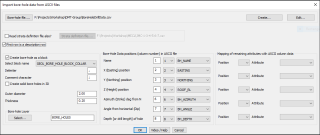
GEOL_STRATABUILDER command – Drawing the bore-hole geometry using Dip & Strike
In this method, your CSV file must have its ground coordinates and the dip-strike information. The same is plotted in CAD as a point (or block with attributes) and the bore hole progression line is shown as a 3d polyline.
GeoTools comes pre-supplied with several bore hole blocks, some are with attributes and some without.
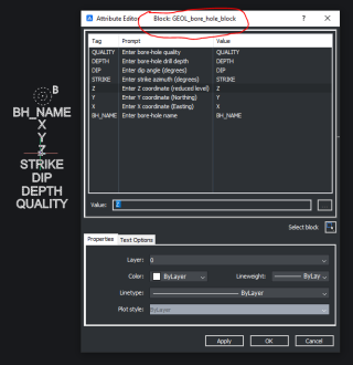
The GEOL_BORE_HOLE block has the following attributes as shown below:
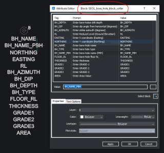
The GEOL_BORE_HOLE_COLLAR block more attributes, and is shown below:
In addition, GeoTools is shipped with a number of other BORE_HOLE blocks as well, and they offer different representation but no attributes.
There are some dynamic blocks as well which allow you to toggle the visibility states as per their quality parameter.
The Roadmap ahead
Going forward, we have great plans to improve the CAD tools to bring in geological exploration data, plot them in CAD, created 3d models out of them and build ore models, reserve planning and so on.
Our journey has just begun and 2021 promises to be a year where we intend to make significant progress in this domain.
We are also happy to announce to you that the Geological and Mining Modules in GeoTools will be spun off as a separate product called TerraMiner in the next 3 months.
CADPower Updates
(Enhancement) CP_SPL2PL: Menu: CADPower -> Conversion -> Lines/Polyline/Arc/Splines -> Convert Splines to polylines:
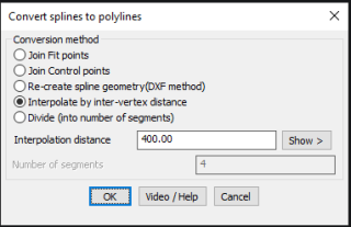
In yet another minor but useful enhancement, a Show option has been added in the CP_SPL2PL command to enable users to show the interpolation distance visually on the screen by picking two points.
This is handy when you have a visual feel of the polyline and its vertices but are not sure of the exact distance in drawing units.
