Linear Quantities and Adding a database to .dwg: CADPower-GeoTools V 16.05 Update
Bengaluru, India
CADPower V 16.05 Update released today
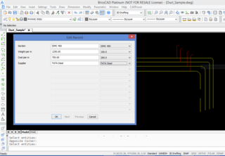
New command added: CP_DATAMAN (CADPower -> Build -> Data Manager): The CP_DATAMAN command is used to define a simple XDATA based database which operates entirely inside your CAD drawing.
All data is stored in XDATA attached to entities and the database definition is provided in a simple INI file.

A sample structure of the INI file looks like this. Explanation about the syntax is provided after each section.
[*RECORD]
Name=BAR_INFO
Type=XDATA
FIELD=Section,String,1000
FIELD=Weight per m,Real,1000.0
FIELD=Cost per m,Real,500.0
FIELD=Supplier,String,Tata
[*RECORD_END]
The [*RECORD]….[*RECORD_END] section defines the database structure. It is defined with lines having <Parameter>=<Value> syntax.
The ‘Name’ parameter specifies the database name (or the XDATA application name).
The ‘Type’ parameter indicates the type of database. In this case, it is ‘XDATA’. In future, additional database types like ‘ATTRIBUTES’ etc will be introduced.
[*FIELD_VALUES]
Name=Section
Values=ISMB 200
Values=ISMB 300
Values=ISMC 400
[*FIELD_VALUES_END]
The [*FIELD_VALUES]….[*FIELD_VALUES_END] section defines the fields structure. This is also defined with <Parameter>=<Value> syntax.
The ‘Name’ parameter specifies the Field Name.
The ‘Values’ parameter defines the commonly used values for the field. These will appear in a pull-down menu when the CP_DATAMAN command is run.
There will be multiple [*FIELD_VALUES] section in the INI file, as many as the number of fields.
However, it is not mandatory to define the [*FIELD_VALUES]. If this section is not defined for a field, there will be no pull-down menu options while entering data for the field.
When you run the CP_DATAMAN command, you are asked for a INI file. This file defines the structure of the database.
As per this structure, the user can enter data via a dialog box interface. If you are editing existing entity data using this command, the data in the entity must be of the same structure as defined in the INI file, else an error is flagged and the command aborts.
New command added: CP_LINEQTY (CADPower -> BOM/BOQ Tools -> Compute linear quantities): In one of my earlier posts, I promised CAD users a tool for computing quantities based on the cost and weight of materials per unit length.
In other words, a Bill of Quantities based on the length as the defining parameter.
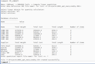
The CP_LINEQTY command provides this feature – a quantity summary using physical length, weight/unit length and cost/unit length as the primary parameters.

All data required comes from XDATA attached to the entity.
The entity can hold additional data also as defined in the INI file, which is created/edited using the using the CP_DATAMAN command.
The CP_LINEQTY command requires data to be structured in such a way that the ‘Weight per unit length’ and ‘Cost per unit length’ are provided as inputs in the INI file. CADPower V 16.05 provides a sample INI file in the install folder (under the SUPPORT sub-folder) which you can use to attach data using CP_DATAMAN command and then generate quantities using CP_LINEQTY command.
New command added: CP_INIEDITOR (CADPower -> Miscellaneous -> File Management-> INI Editor): The CP_INIEDITOR command is used to edit INI files used by various CADPower commands.
While some of the commands have a built-in access to an ‘Edit’ button, many don’t. If you need to edit an INI file, you can use this tool.
New command added: CP_PATTERNPLACER: (CADPower -> Draw -> Symbology -> Pattern Placer): The CP_PATTERNPLACER command is used to arrange a pattern inside a polygonal boundary in a row-wise manner.
The command works with blocks. You must first create a block that represents one motif of the repeating pattern.
The motif must be drawn in a direction facing the CAD 0 degree direction (east) and the insertion point must be at the left hand center of the motif.
The 0 degree direction of the motif becomes the flow direction when the pattern is generated on a repeated basis along the row.
An X and Y offset is specified to denote where the next row will be positioned (alignment with reference to the adjacent row).
Another distance parameter indicates the distance between the two motifs along the row.
New maintenance command added (BricsCAD only): The CP_ENVSET command is used to offer a clean user-interface in BricsCAD when moving from one work-space to another.

BricsCAD has introduced certain defaults and pre-sets in the user-interface when the Mechanical and BIM work-spaces are activated.
For example, the BIM work-space hides the command line and the Mechanical work-space hides the pull-down menu completely.
Some of the common drafting toolbars are not visible as well. In addition, any custom partial menu that is attached (like GeoTools & CADPower) switches on all toolbars automatically when work-spaces are switched.
The CP_ENVSET command offers a clean and consistent environment when the work-spaces are switched.
This is based on user-feedback we obtained from majority users in India.
The following are some of the preset operations done by CP_ENVSET:
- Pull-down menu bar is switched on
- GeoTools & CADPower toolbars are hidden and not displayed
- ‘Entity Properties’, ‘Work-spaces’ and ‘View’ toolbar are switched ON
- The CommandLine is switched on
Based on feedback, we have identified these as some of the commonly required look-and-feel users expect upon work-space change.
We are keen to hear from our users if they require anything more, less or different.
