GeoTools-CADPower V 19.04 Update: Improved Area Calculations, Region-wise Quantities, Section Offsets, Geological Tools & More
Bengaluru, India
*** CADPower V 19.04 Update
** Enhanced command: CP_BOM (CADPower -> BOM/BOQ Tools -> Create Bill of Materials/Quantities):
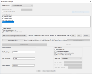
Two new options have been added to this command to generate quantities based on a per-polygon basis.
Until now, the block name count and attribute extraction was based on the selected objects, irrespective of how they were placed. The CP_BOM command now has two additional options:
- Attribute Extraction(per polygon)
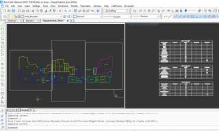
- Multiple Named Blocks(per polygon)
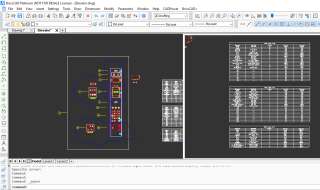
Upon selecting these two options, the command now makes a selection of blocks within each polgon and presents the quantities in a separate table of its own.
This option was added based on a feedback from a user who wanted to generate room-wise quantities in an architectural drawing based on closed polylines which represented different room areas.
** Enhanced command: CP_CALCAREA (CADPower-> Polyline-> Inquiry Statistics-> Compute summed areas of closed polylines):
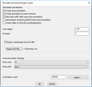
The CP_CALCAREA command now has an option to determine if the polygon numbering must appear along with the area annotation or not.
If this option is chosen, each polygon is numbered as 1, 2, 3… and the same is displayed in the table as well. The option to control the numbering in the drawing offers better control over how the output is presented.
The numbering in the table is logical and appears always. If you don’t want it in the table, simply delete the column.
*** GeoTools V 19.04 Update
** Enhanced command: GT_3DOFFSETSECTION (GeoTools -> Build -> Offset 3d polylines along section):
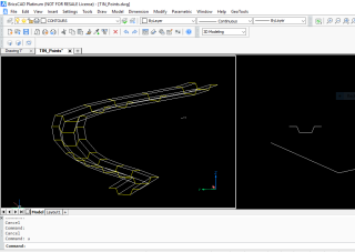
Output from GT_3DOFFSETSECTION comand
The GT_3DOFFSETSECTION command has been significantly improved and bug-fixed as well. It is used to offset a 3d (or even 2d) polyline along the defining points of a 2d cross-section, in such a way as to create a 3d model of the same.
This is an extension of the existing GT_3DOFFSETSLOPE command that where only one side slope can be defined. The section option sweeps a 2d cross-section along a 3d (or 2d) polyline in such a way that a full 3d model is generated.
It is also possible to create a 3D DTM of the swept path surface using 3dface objects.
This tool is very handy to sweep the cross-section of a road or an irrigation channel or a duct along an extrusion path (or long section in case of civil projects) and create a 3d section of the same very quickly.
The generated output are 3d polylines which are useful in design calculations or 3dface objects that are useful in visualization.
** Enhanced command: GEOL_PLACEDIPSTRIKESYMBOL (GeoTools -> Mining & Geological Tools -> Dimensional Stone Tools -> Place dip/strike symbols):
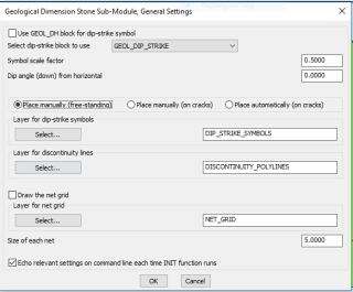
The GEOL_PLACEDIPSTRIKESYMBOL command has been enhanced to enable placing of a dip-strike symbol at a free standing (blank) location also. Until now,
you could only place along existing cracks.
The GEOL_PLACEDIPSTRIKESYMBOL command is used to place a dip / strike symbol.
This is a block which has a default name of GEOL_DIP_STRIKE and is stored in the GeoTools installation folder. It has a standard dip/strike symbol representing two perpendicular lines, representing the dip and strike directions. The dip direction is the shorter of the two.
GeoTools comes pre-defined with three dip-strike blocks:
- GEOL_DIP_STRIKE: This is the default block defined by GeoTools. It has two attributes: DIP_ANGLE_FROM_HOR and DIP_AZIMUTH,and has its rotation angle drag direction along the strike direction.
- GDH1_DIP_STRIKE: This is a block which has been copied from a now-defunct Geology software called GEOL_DH which is popular in some parts of East Europe. This block does not contain any attributes and has its rotation angle drag direction along the dip direction.
- GDH2_DIP_STRIKE: This block is similar to the GDH1_DIP_STRIKE block but defines two attributes: DIP_ANGLE_FROM_HOR and DIP_AZIMUTH and has its rotation angle drag direction along the dip direction.
Do not modify the geometric definition (orientation) of these blocks as the program depends on its original definition and orientation to compute the dip and strike azimuths.
The command allows you to place dip and strike symbols in three different modes:
- Place manually (Free Standing)
- Place manually (on cracks)
- Place automatically (on cracks)
Place manually (free standing): Choosing this option allows you to place the dip-strike symbol on a blank area. For this command to be effective (and correct), you must choose the block named GDH2_DIP_STRIKE or GDH1_DIP_STRIKE.
Place manually (on cracks): Choosing this option allows you to place the dip-strike symbol manually on an existing crack.
A crack is defined as a polyline, line or spline entity which progresses from one point to another along the terrain. For this command to be effective (and correct), you must choose the block named GDH1_DIP_STRIKE or GEOL_DIP_STRIKE.
Place automatically (on cracks): Choosing this option allows you to place the dip-strike symbol automatically on existing cracks.
A crack is defined as a polyline, line or spline entity which progresses from one point to another along the terrain.
Multiple cracks can be selected and the command will place the dip-strike symbols along them.
For this command to be effective (and correct), you must choose the block named GDH1_DIP_STRIKE or GEOL_DIP_STRIKE. In this mode, the command will place dip/strike symbols across a selection of cracks with a condition that at least one symbol is placed within a defined square window (which is also called the net size).
You must select crack/discontinuity lines and also specify the layers where the cracks, net grid etc. must be created and the dip/strike symbol will be created accordingly.
Please be aware that the dip and strike azimuths are implicitly stored in the direction/angle of insertion of the block.
The direction of the longer line determines the strike direction, and the direction of the shorter perpendicular line determines the azimuth direction.
The inclination of the dip (the angle it makes with the horizontal) is stored as an attribute DIP_ANGLE_FROM_HOR within the block.
It needs to be manually entered by the user using either attribute edit commands or using either any of the tools provided in GeoTools or in the GEOL_PLACEDIPSTRIKESYMBOL command dialog box itself.
** New command added: GEOL_UPDATEDIPAZIMUTH: GeoTools -> Geological / Mining Tools -> Dimensional Stone Tools Update Dip Azimuth attribute values):
The GEOL_UPDATEDIPAZIMUTH command is used to update the dip azimuth attribute value in the block based on the current rotation angle of the dip-strike block.
The program identifies the block based on its name and determines how the value must be correctly updated.
Want to know more about DesignSense, BricsCAD?
- BricsCAD V18: Trial download
- BricsCAD V18 Shape: Free download
- BricsCAD Communicator V18: Trial download
- CADPower V19 for BricsCAD: EXE (-or-) ZIP (Linux/Mac compatible)
- CADPower V19 for AutoCAD: EXE (-or-) ZIP
- GeoTools V19 for BricsCAD: EXE (-or-) ZIP (Linux/Mac compatible)
- GeoTools V19 for AutoCAD: EXE (-or-) ZIP
Key Contacts: rakesh.rao(at)thedesignsense.com / +91-9243438300 / +91-8073279755
Follow us on Twitter: http://www.twitter.com/rakesh_rao
