Using AutoCAD and BricsCAD V23 for Surface Area Calculations using CADPower

CADPower V 23.32 Update
Using AutoCAD and BricsCAD V23 for Surface Area Calculations

Step by step workflow for area computation and quantity take-off.


One of the most tedious tasks for any construction professional is to compute quantity takeoff from your construction drawings. Sketching a plan and drawing the building may be your main design objective but creating cost estimates and good-for-construction data is also a major follow-up task by itself.


CADPower has always had a set of disparate tools to achieve this in bits and pieces but we have now stitched together a workflow that will enable you to complete these tasks faster than before.


In this post, I will go through this process step-by-step and show you a workflow that I believe would be a starting point for further automation and improvements.


We start with a room, which has a set of walls, typically four but could be more as well. A typical room in CAD would be available as a closed polyline. The first step would be to draw the walls in elevation, as a developed view.


We start with this step and will use the CP_BUILDWALLS command to do that. It is available under the BOM/BOQ Tools.

CP_BUILDWALLS is where you start your wall area management

The CADPower CP_BUILDWALLS dialog box


In the example above, we start with a simple closed polyline that represents the plan footprint of the room. It is drawn with mm as the drawing units and shows an L-shaped room with one of the walls having a semi-circular curvature.


I have used the CP_SEGLABEL (CADPower -> Annotation -> Label polyline segments) command to create the wall length labels as text objects in millimeters.


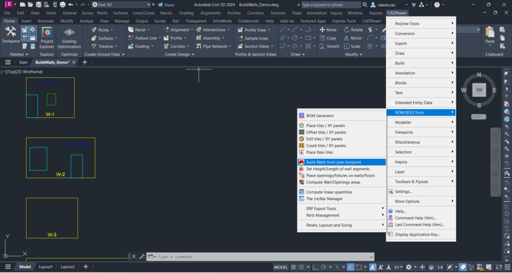
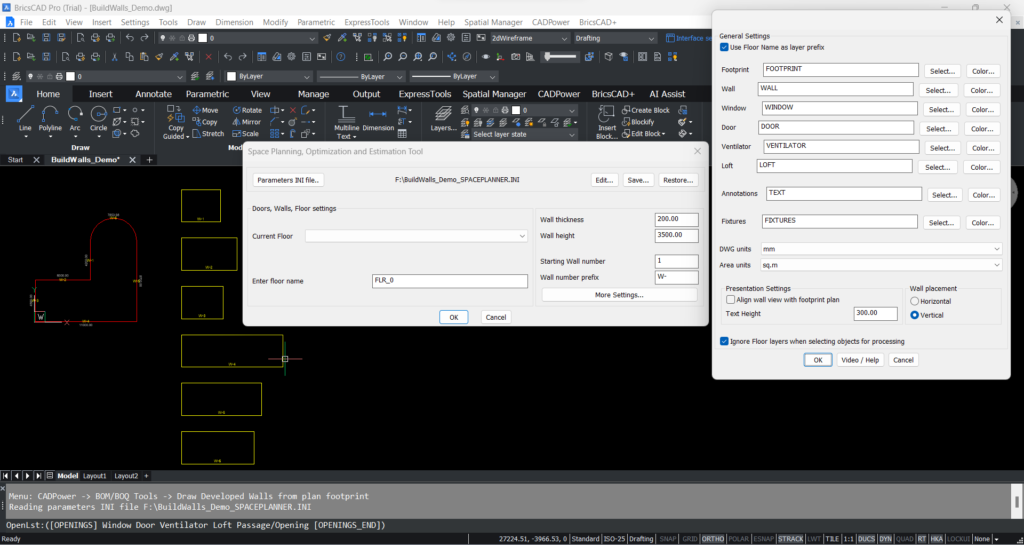
Next, I use the CP_BUILDWALLS (CADPower -> BOM/BOQ Tools -> Draw Developed Walls from plan footprint) command to create the elevation view of each wall. In the first dialog box, you have set the wall thickness and the height. This command operates in millimeters by defaults, and the suggested defaults values are shown. If you work in meters, please remember to change all your units accordingly, else your output will look incorrect. I specify the Wall prefix as W-, so that I get the wall names as W-1, W-2 and so on. You can also specify the floor name here, which will form the basis for your layer names throughout your design.


If you click on More Settings…, another dialog box will open up which allows you set more operating parameters like layers, drawing and area units, text heights etc.


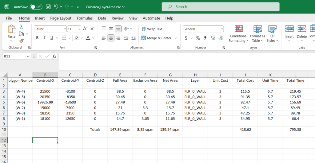
I have chosen mm as my drawing unit but sq.m as my area units, since it makes more sense for me to state my wall areas in square meters.


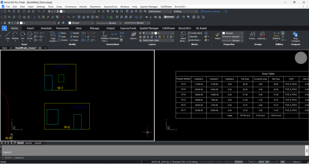
Upon clicking Ok, I am now prompted to select a point where I want to start drawing the walls.


Each wall is now drawn in elevation as a rectangle (close polyline), with the wall name appearing as a text inside the polyline.


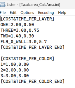
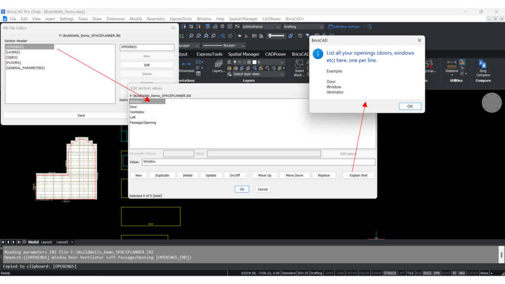
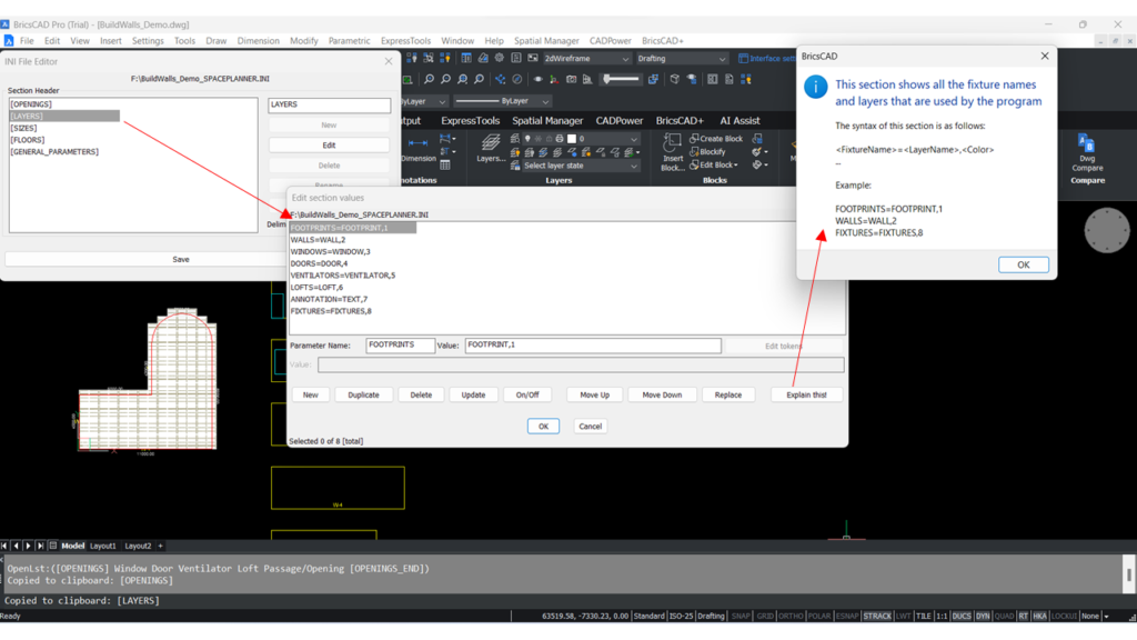
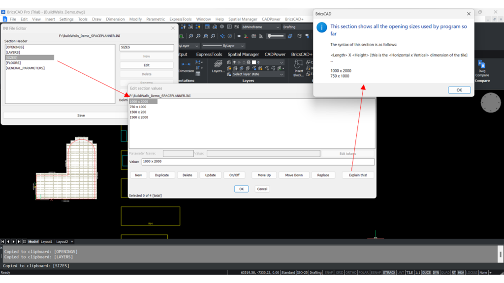
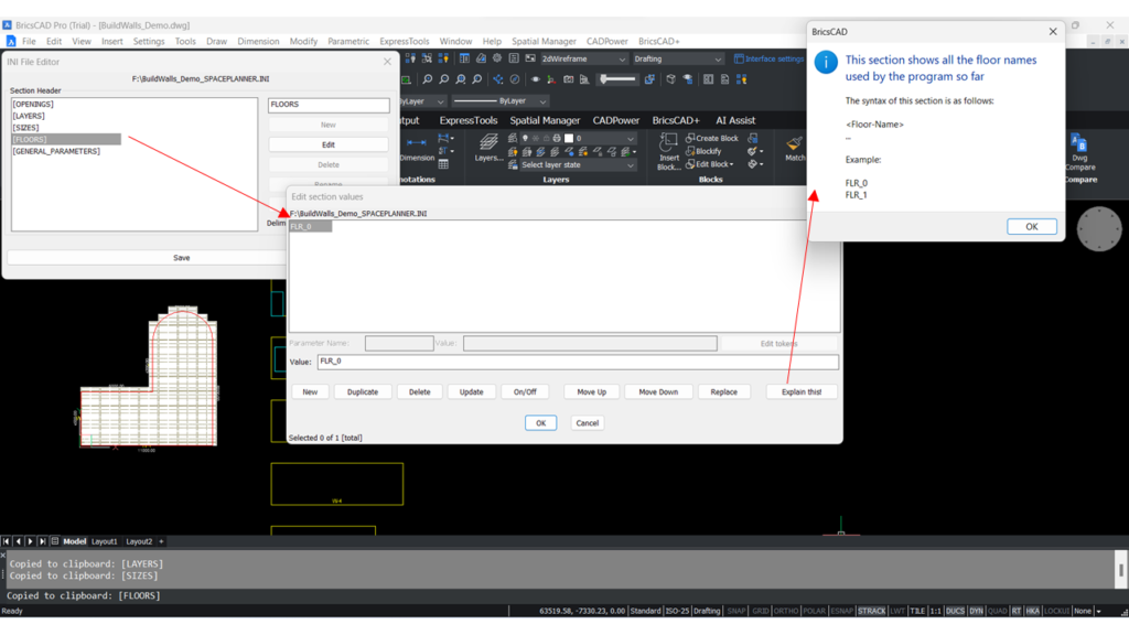
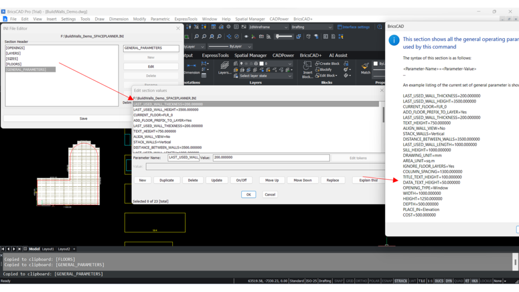
The CP_BUILDWALLS command stores all its operating parameters in an INI file, whose name is shown in the dialog box. It is a simple ASCII file and you can maintain multiple such files for each project that you are working on.


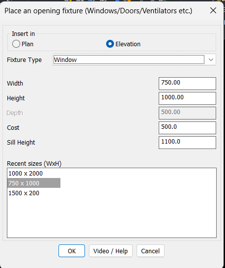
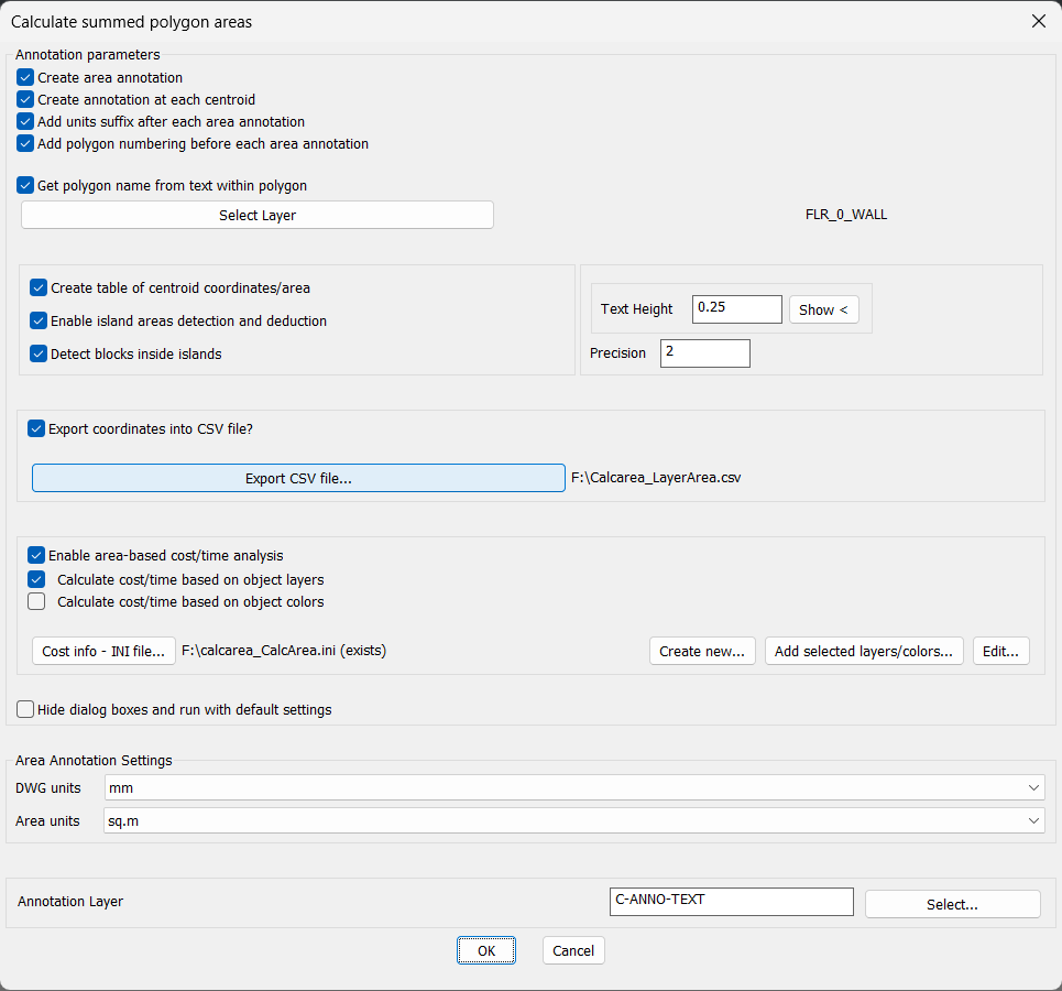
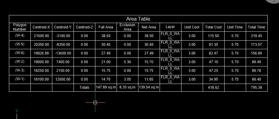
These walls in elevation are closed rectangular polylines, but you can edit them manually to suit your design conditions. The summed area of all these walls will be the total surface area of your walls for this room. In the next steps, we will see how we can specify a window, door, loft or an opening on these walls, and how the will affect your area computations.


Placing your fixtures - Windows, Doors, Lofts, Ventilators, Openings

The CP_PLACEFIXTURES command in CADPower allows placing simple walls, windows and lofts within wall elevation polylines

The next task is to place fixtures that adorn your wall. You can use the CP_PLACEFIXTURES (CADPower -> BOM/BOQ Tools -> Place Openings) command which displays a default set of fixtures like doors, windows and lofts. You can add your own custom fixtures by editing the INI file in the [OPENINGS] section. Sizes for your fixtures that you specify here get automatically saved to the INI file in the [SIZES] section such that they can be easily picked and re-used without having to re-enter the values.

The fixtures that you place here get auto-detected inside the wall polyline, so they get placed in the correct layers. For example, if the floor name is FLR_0, the walls are placed in FLR_0_WALL layer, and the doors are in FLR_0_DOOR layer.

Computing the nett. area table and exporting to Excel

The CP_CALCAREA command is a polygon-based area computation tool in AutoCAD and BricsCAD

The CP_CALCAREA (CADPower-> Polyline-> Inquiry Statistics-> Compute summed areas of closed polylines) command works primarily with closed polyines, computes the areas and reports the same in CAD tables and in Excel CSV format. In this conext, we need the nett. area of a wall, which is the total wall area minus the areas of fixtures. For cost and quantity estimation of things like painting, tiling and panel area, the exclusion areas have to be deducted.

This is easily enabled in the command by clicking on the option ‘Enable island areas detection and deduction’ and ‘Detect blocks inside islands’.

The first option is self-explanatory. Checking the option causes the polygons to be sorted (from largest to smallest area) and any polyline inside  the larger polyline will be deducted for area computation. Checking the ‘Enable blocks inside islands’ option will also detect CAD blocks within the polyline and deduct their areas. The second option allows the output from CP_BUILDWALLS and CP_PLACEFIXTURES commands to be processed easily by the CP_CALCAREA command.

The CP_CALCAREA command is very flexible and allows the reporting of areas to be controlled precisely. You can specify drawing units and area units differently (if required), this helps to create customizable area reports.

You can get the polygon name from within by checking the option ‘Get polygon name from text within polygon’. This enables you to display the wall name in your table in our current context of area names.


In the example above, you can see that the areas of fixtures found inside the wall polygons W-1 and W-2 are deducted from their enclosing polygon. The resulting areas (total, exclusion and nett. area) are shown in the table, along with the totals.

Enabling cost and time analysis

The CP_CALCAREA command has another important feature that you will find useful. You can click on the ‘Enable area-based cost/time analysis’. This will allow you to compute the cost and time estimates for your polygons based on a per-layer or per-color basis.


Setting cost and time parameter in CADPower Quantity takeoff for AutoCAD
CADPower generated Excel CSV file showing cost and time analysis in BricsCAD

The INI file for the CP_BUILDWALLS command have several sections, but it easy to understand, with a little help

The Openings section of the CP_BUILDWALLS INI file in CADPower
The LAYERS section in the CP_BUILDWALL INI file of CADPower
The SIZES section of CP_BUILDWALLS INI command of CADPower
The FLOORS section of the C_BUILDWALLS INI file of CADPower

Screen-grab showing how the contents of each section of the CP_BUILDWALLS INI file is constructed

Using AutoCAD and BricsCAD V23 for Surface Area Calculations using CADPower

Leave a Reply

Your email address will not be published. Required fields are marked *